Vehicle with switched supplemental energy storage system for engine cranking

Active Publication Date: 2005-03-29
KOLD BAN INT
View PDF53 Cites 21 Cited by
  • Summary
  • Abstract
  • Description
  • Claims
  • Application Information

AI Technical Summary

Benefits of technology

The various preferred embodiments provide significant advantages over other engine cranking systems. In particular, the capacitor is completely isolated when the ignition switch is not in the start position. Accordingly, the capacitor cannot be inadvertently discharged, and it can

Problems solved by technology

A problem presently exists with vehicles such as heavy-duty trucks.
Drivers may on occasion run auxiliary loads excessively when the truck engine is not running.
Excessive use of such appliances can drain the vehicle batteries to the extent that it is no longer possible to start the truck engine.
Often, however, the capacitor is not completely isolated, and can lose its

Method used


Image

  • Vehicle with switched supplemental energy storage system for engine cranking
  • Vehicle with switched supplemental energy storage system for engine cranking
  • Vehicle with switched supplemental energy storage system for engine cranking

Examples


Embodiment Construction

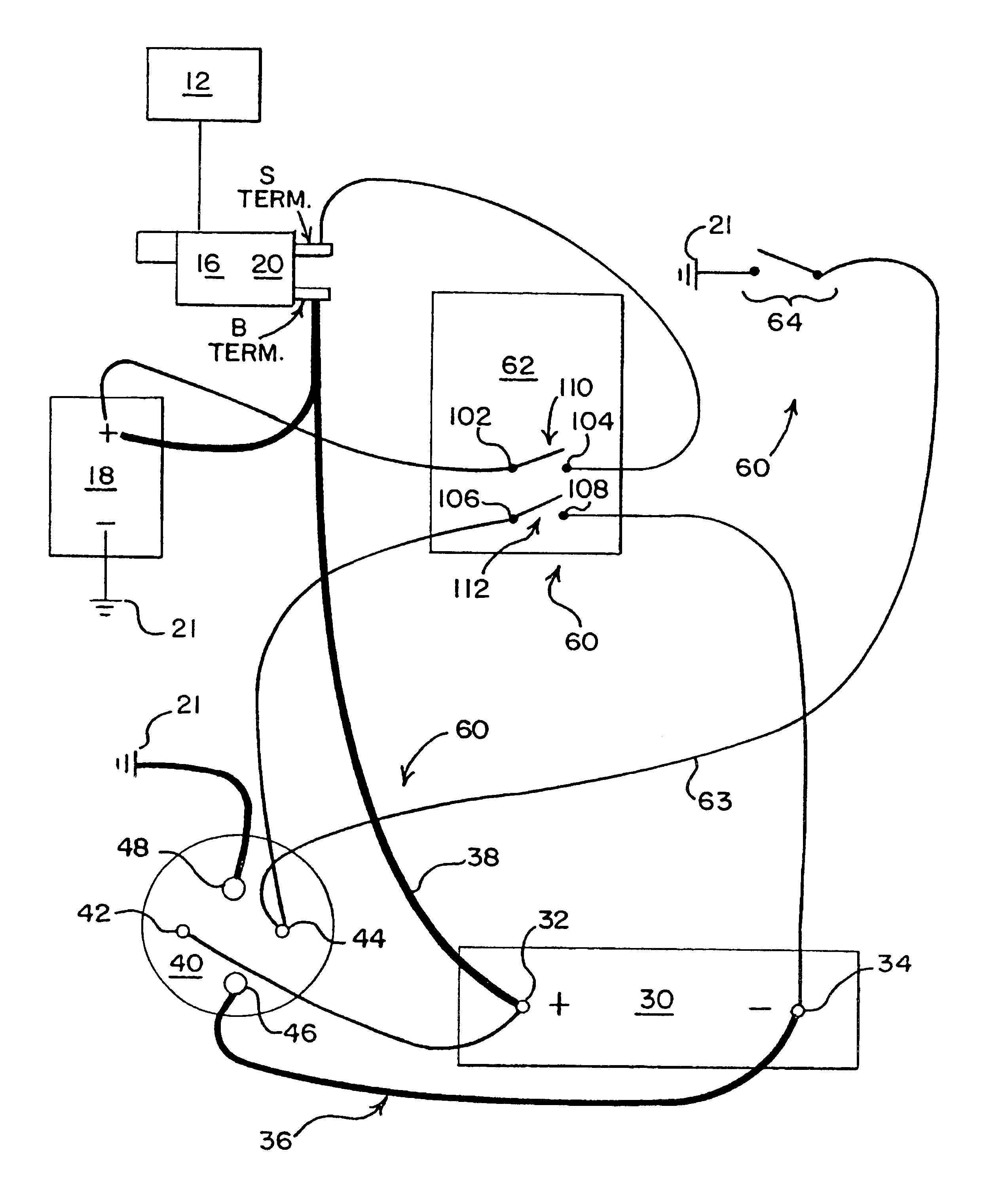
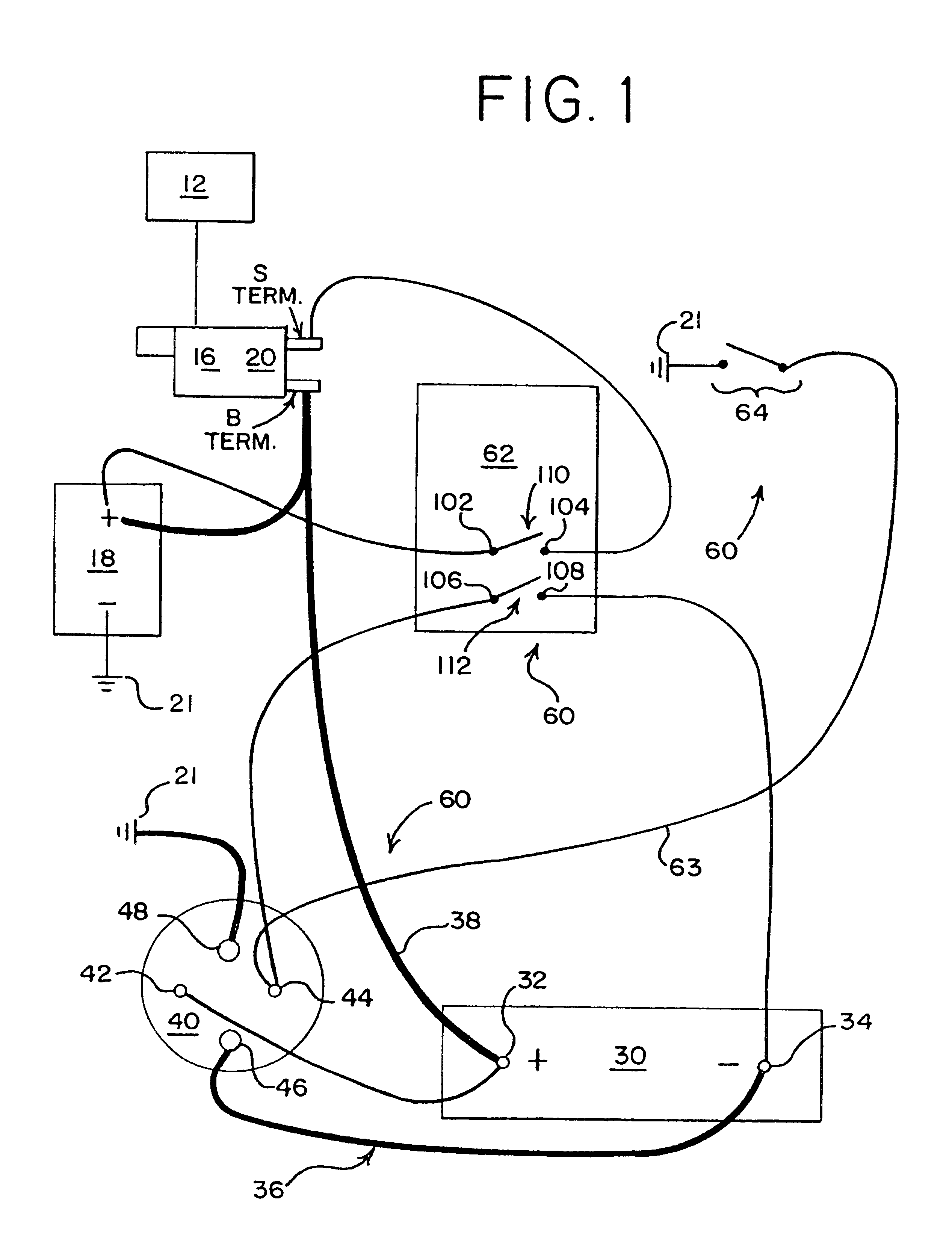
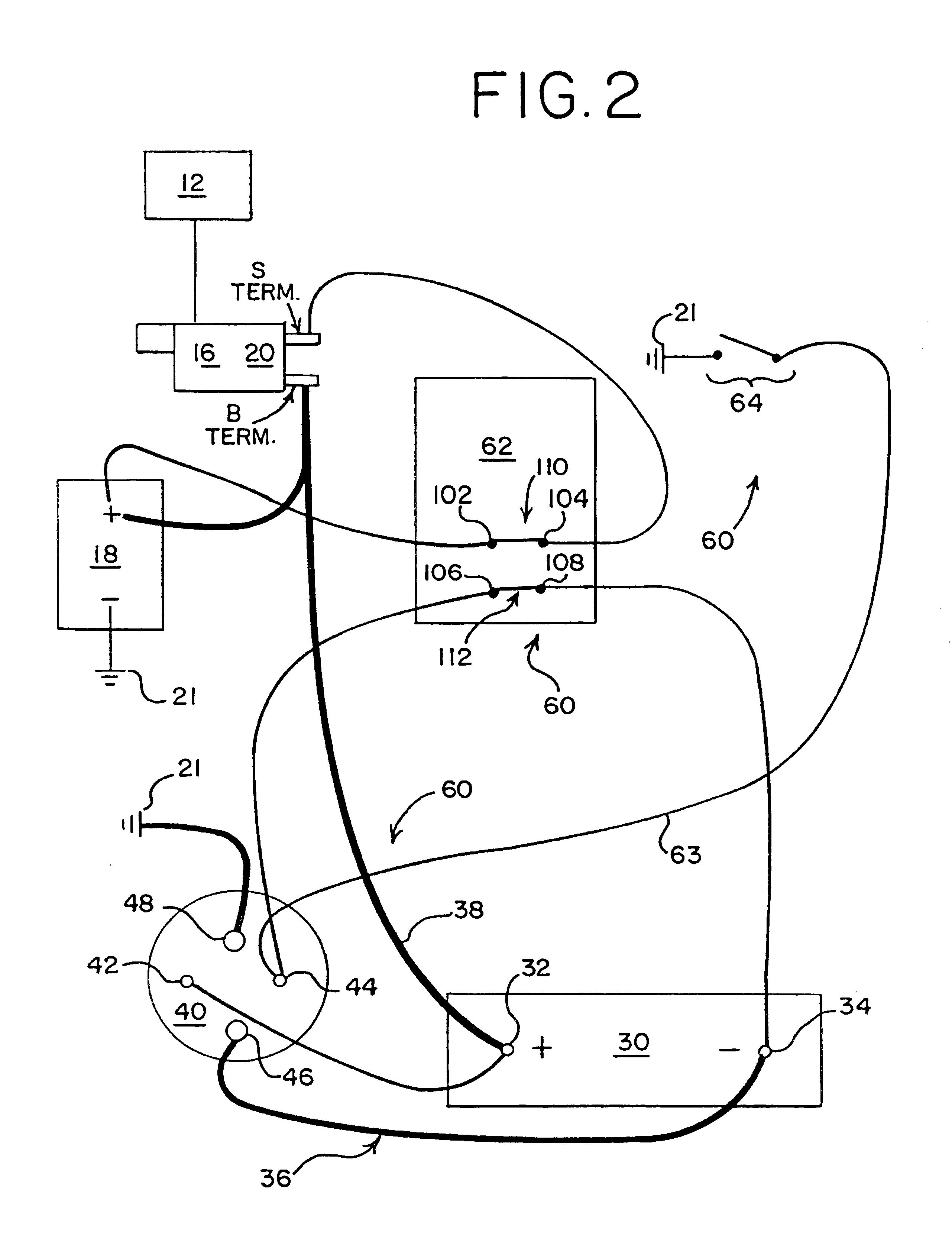
Turning down to the drawings, FIGS. 1-4 show an electrical system of a vehicle (not shown) that includes an internal combustion engine 12. The engine 12 can take any suitable form, and may for example be a conventional diesel or gasoline engine. The engine 12 is mechanically coupled to a cranking motor 16. The cranking motor 16 can take any suitable form, and it is conventionally an electrical motor that is powered during cranking conditions by current from one or more storage batteries 18 such as conventional lead-acid batteries. Current from the batteries 18 is switched to the cranking motor 16 via a switch such as a conventional solenoid switch 20. In operation, the engine is operably moved between a running condition and an off condition.

All of the elements 12 through 20 described above may be entirely conventional, and are well-known to those skilled in the art. The present invention is well adapted for use with the widest variety of alternative embodiments of these elements.

In ad


PUM


Abstract

An engine cranking system includes an engine, a cranking motor coupled to the engine and a battery having first and second battery terminals. The first battery terminal is electrically coupled to the cranking motor and the second battery terminal is electrically coupled to a system ground. A capacitor includes first and second capacitor terminals. First and second electrical paths interconnect the first and second capacitor terminals, respectively, with the cranking motor and the system ground. First and second switches include first and second sets of switch terminals respectively. The first set of switch terminals is coupled between the first battery terminal and the cranking motor. A relay is included in one of the first and second electrical paths and has first and second control terminals. The second set of switch terminals is coupled between one of the first and second capacitor terminals and the second control terminal. The other of the first and second capacitor terminals is electrically coupled with the first control terminal. The relay is moveable between at least a closed-circuit position, in which the relay completes one of the first and second electrical paths, and an open-circuit condition, in which the relay interrupts one of the first and second electrical paths. In one embodiment, a running engine sensory component is coupled between one of the system ground and the first battery terminal and one of the first and second control terminals. The running engine sensory component maintains the relay in the closed-circuit position when the engine is running.

Description


Claims


Application Information

Patent Timeline
Owner KOLD BAN INT
Why Eureka
Try Eureka