Differential protection d-side phase-shift current phase compensation method for YNd3 transformer

A technology of current phase compensation and differential protection, applied in the direction of emergency protection circuit devices, electrical components, etc., can solve the problem that YNd3 transformers cannot use software phase shifting methods, etc., to improve the accuracy of current phase compensation, improve accuracy, and avoid The effect of misuse

Inactive Publication Date: 2017-05-31
STATE GRID JIANGSU ELECTRIC POWER CO ZHENJIANG POWER SUPPLY CO
View PDF7 Cites 0 Cited by
  • Summary
  • Abstract
  • Description
  • Claims
  • Application Information

AI Technical Summary

Benefits of technology

This patented technology improves upon existing methods used during current phase correction calculations when there are no errors or changes made at any points along their way (such as due to electrical noise). By utilizing this new technique instead of relying solely on previous measurements, more accurate results may be achieved even if some parts have changed over time.

Problems solved by technology

This patented technical problem addressed in this patent relates to improving the accuracy and reliability of current phase correction techniques when utilizing different types or combinations of components within an overall protective system. Current phase corrections are performed through analog circuits that have limitations such as variations caused by temperature changes over time. To address these issues, there has been developed various digital processing technologies called Digital Phase Lock Looping ("DPLL"), which uses advanced technology to correct errors introduced during transmission without affecting any important parts of the protected equipment.

Method used


Image

  • Differential protection d-side phase-shift current phase compensation method for YNd3 transformer
  • Differential protection d-side phase-shift current phase compensation method for YNd3 transformer
  • Differential protection d-side phase-shift current phase compensation method for YNd3 transformer

Examples


Embodiment Construction

[0030] In order to more clearly illustrate the embodiments of the present invention or the technical solutions in the prior art, the specific implementation manners of the present invention will be described below with reference to the accompanying drawings. Obviously, the accompanying drawings in the following description are only some embodiments of the present invention, and those skilled in the art can obtain other accompanying drawings based on these drawings and obtain other implementations.

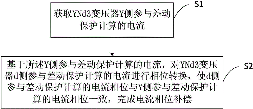
[0031] Such as figure 1 Shown is a YNd3 transformer differential protection d-side phase-shifting current phase compensation method provided by the present invention.

[0032] S1: Obtain the current of the Y side of the YNd3 transformer participating in the differential protection calculation;

[0033] S2: Based on the current involved in the calculation of the differential protection on the Y side, perform phase conversion on the current involved in the calculation of the different


PUM


Abstract

The invention provides a differential protection d-side phase-shift current phase compensation method for an YNd3 transformer, specifically a method for phase compensation of d-side phase-shift current of a differential protection device of an YNd3 wiring transformer. The method includes the steps of firstly obtaining Y-side current participating in differential protection calculation, obtaining the phase of the Y-side current participating in differential protection calculation, conducting phase shift through software for d-side current participating in differential protection calculation to obtain the current phase of the d-side current participating in differential protection calculation consistent with the current phase of the Y-side current participating in differential protection calculation. Rapid and convenient current phase compensation for differential protection of a YNd3 transformer can be realized through a software phase shift method.

Description


Claims


Application Information

Patent Timeline
Owner STATE GRID JIANGSU ELECTRIC POWER CO ZHENJIANG POWER SUPPLY CO
Why Eureka
Try Eureka