Drive device for twin-screw extruder

A twin-screw extruder and driving device technology, which is applied in the direction of mechanical equipment, bearings, liquid cushion bearings, etc., can solve problems such as inapplicability, and achieve the effect of increasing life and shortening length

Active Publication Date: 2017-06-16
レンクゲーエムベーハー
View PDF8 Cites 2 Cited by
  • Summary
  • Abstract
  • Description
  • Claims
  • Application Information

AI Technical Summary

Benefits of technology

The technical effect of this new design is that it allows for longer lifespan without requiring more expensive components like ball or roller bearings due to its use of hydraulic support instead of traditional rolling elements.

Problems solved by technology

Technicelions: The technical problem addressed in this patented describes various configurations used in driving mechanisms (shuttle motors) associated with different types of conveyor systems including roller type conveyance devices. One solution involves connecting certain components together through weld joints called spline couplings, allowing them to rotate freely around respective axes while still being able to transmit torque therebetween. Another option includes incorporate planar gears instead of solid metal meshed gears but these alternatives result in increased complexity and cost compared to traditional designs.

Method used


Image

  • Drive device for twin-screw extruder
  • Drive device for twin-screw extruder
  • Drive device for twin-screw extruder

Examples


Embodiment Construction

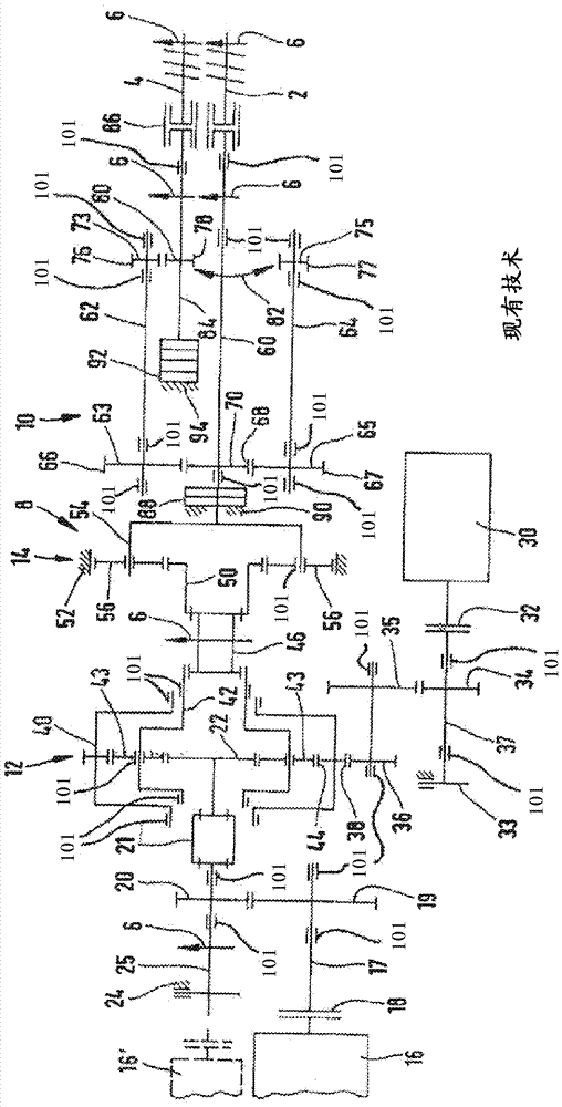
[0018] The invention relates to a drive for a twin-screw extruder. The construction of drives for twin-screw extruders is well known to those skilled in the art mentioned here and is known from DE 10 2004 051 306 B4. Accordingly, the drive means for the twin-screw extruder comprises at least one electric motor 16, 16', 30, wherein each motor acts on a drive or input shaft 17, 25, 37. Furthermore, the drive of the twin-screw extruder comprises a plurality of output shafts 60 , 84 , wherein the screw shaft 2 , 4 of the twin-screw extruder is coupled to each drive shaft 60 , 84 .

[0019] A planetary gear assembly 8 with at least one planetary gear stage and a gear assembly configured as a power split transmission 10 is connected between the or each drive or input shaft 17 , 25 , 37 and the output shaft 60 , 84 .

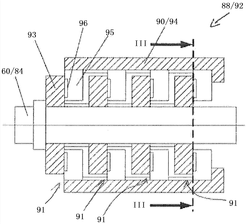
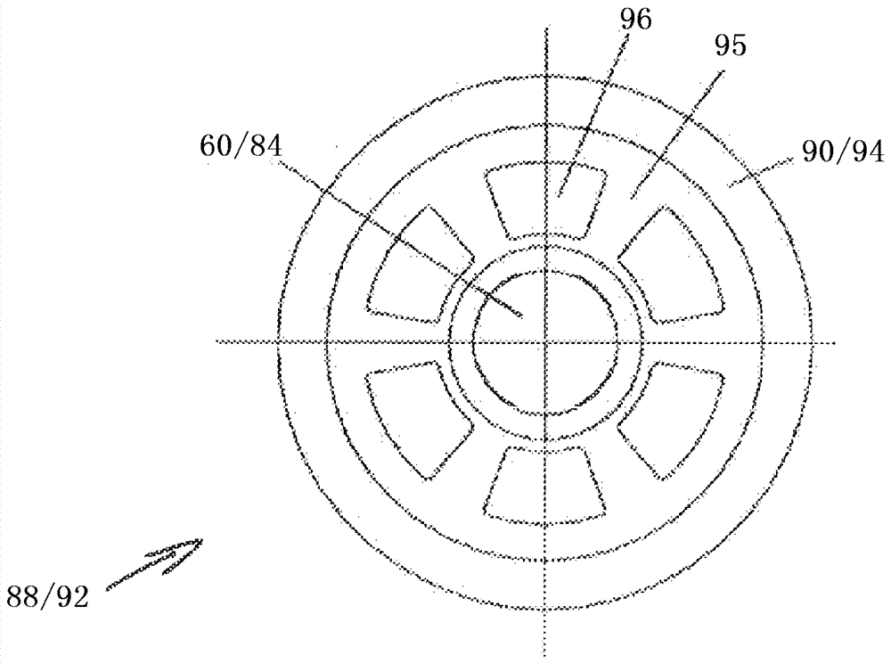
[0020] The invention concerns these details of the drive for a twin-screw extruder, with which an advantageous axial support of the two output shafts 60 , 84 of the


PUM


Abstract

The invention relates to a drive device for a twin-screw extruder. The drive device comprises at least one input shaft (17, 25), to which a motor (16, 16') can be coupled; a first output shaft (60) to which a first screw shaft of the twin-screw extruder can be coupled; a second output shaft (84) to which a second screw shaft of the twin-screw extruder can be coupled; a planetary gearing group (8); and a power division transmission (10). The output shafts (60, 84) are arranged in radial bearings (101) on the one hand and in axial main bearings (88, 92) for withstanding axial thrust on the other hand. The axial main bearings (88, 92) of the output shafts (60, 84) are designed as hydrostatically supported axial sliding bearings.

Description


Claims


Application Information

Patent Timeline
Owner レンクゲーエムベーハー
Why Eureka
Try Eureka