Frame body device of movable bridge frame molding machine

A mobile and forming machine technology, applied in cleaning methods, road surface cleaning, workshop equipment, etc., can solve problems affecting work efficiency, different floor space, easy to shake, etc., to improve work efficiency, ensure processing effect, The effect of not deforming the structure

Inactive Publication Date: 2017-06-20
姜宗娥
View PDF0 Cites 0 Cited by
  • Summary
  • Abstract
  • Description
  • Claims
  • Application Information

AI Technical Summary

Problems solved by technology

[0002] The bridge is a bracket for supporting and placing cables. It has the characteristics of complete varieties, wide application, high strength, light structure, low cost, and simple construction. The floor area is also different. When forming the bridge frame, it needs to consume a lot of manpower and material resources to tran

Method used


Image

  • Frame body device of movable bridge frame molding machine

Examples


Embodiment Construction

[0012] Below in conjunction with accompanying drawing, the present invention will be described in further detail:

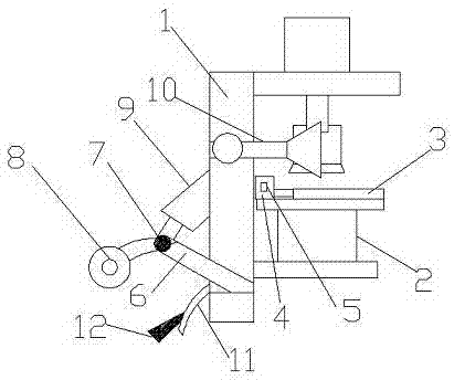
[0013] Such as figure 1 As shown: a frame device of a mobile bridge forming machine in this embodiment, including a mobile frame body 1 and a pad frame 2, the bottom of the pad frame 2 is embedded and fixed on the mobile frame body 1; The top of the pad platform 2 is a movable plate 3, and one end of the movable plate 3 is connected and fixed with the first cylinder 4; the infrared sensor 5 is fixed on the first cylinder 4; The two ends of the bottom extend the support arms 6, and the two support arms 6 are connected and fixed by the rotating shaft 7. The end of the rotating shaft 7 is connected with a moving wheel 8 and the middle part is connected and fixed with the second cylinder 9; 1 is provided with clamp arms 10 for rotation on both sides.

[0014] A push plate 11 is provided at one end of the bottom of the movable frame body 1; the rear end of the push pla


PUM


Abstract

The invention provides a frame device of a mobile bridge forming machine, comprising a mobile frame and a pad platform, the bottom of the pad frame is embedded and fixed on the mobile frame body; the top of the pad frame is A movable plate, one end of the movable plate is connected and fixed to the first cylinder; the infrared sensor is fixed on the first cylinder; two ends of the bottom of the mobile frame extend support arms, and the two support arms pass through the rotating shaft The connection is fixed, the end of the rotating shaft is connected with a moving wheel and the middle part is connected and fixed with the second cylinder; the two sides of the movable frame body are rotated and provided with clamping arms. The beneficial effect of the invention is that the design is reasonable, the structure is stable and does not deform; the work efficiency is improved and the processing effect is guaranteed.

Description


Claims


Application Information

Patent Timeline
Owner 姜宗娥
Why Eureka
Try Eureka