Reactive compensation circuit based on improved Buck-boost alternating current chopper
A compensation circuit, chopper technology, applied in reactive power compensation, reactive power adjustment/elimination/compensation and other directions, can solve the problem of high cost and achieve the effect of overcoming the narrow adjustment range
- Summary
- Abstract
- Description
- Claims
- Application Information
AI Technical Summary
Benefits of technology
Problems solved by technology
Method used
Image

Examples
Embodiment Construction
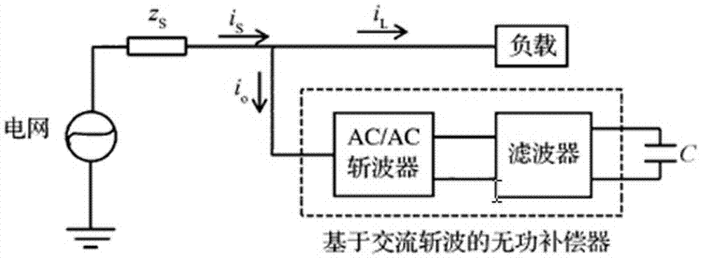
[0015] exist figure 1 Among them, the AC chopper reactive power compensator is mainly composed of three parts: grid side filter, AC / AC chopper and compensation capacitor.
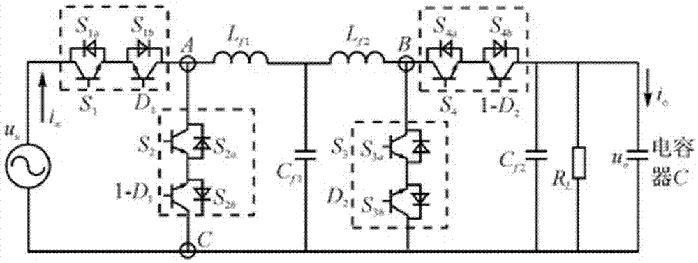
[0016] exist figure 2 Among them, , and,——a bidirectional switch composed of two IGBTs in reverse series, which are complementary to each other; inductance—energy storage inductance;——filter the high-order harmonic components of the switching frequency and its multiples.
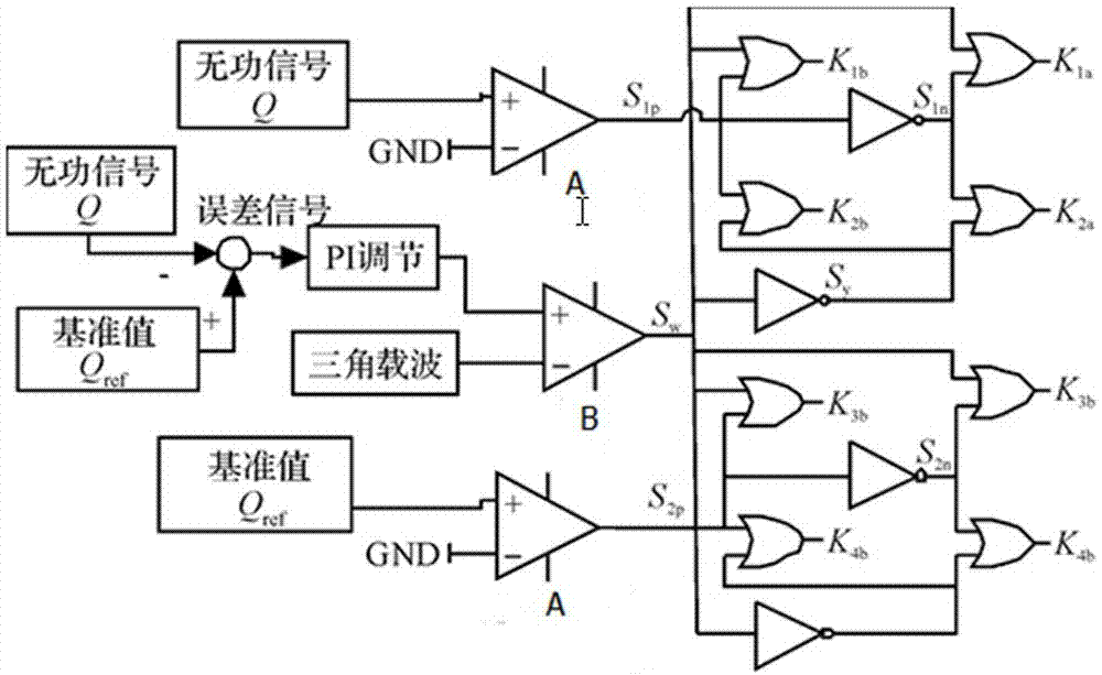
[0017] exist image 3 , Figure 4 Among them, A is the zero-crossing comparator, and B is the comparator (B1, B2 are the corresponding comparators respectively). In the improved Buck-boost chopper circuit, due to the existence of the filter mode, in addition to the reactive power reference value, two other reference values should be set. And a slight change on the basis of the Buck and Boost type AC chopper control circuit , you can complete the precise control of the three modes after the improvement. The specific process is: comp
PUM
 Abstract
Description
Claims
Application Information
 - R&D Engineer
- R&D Manager
- IP Professional
- Industry Leading Data Capabilities
- Powerful AI technology
- Patent DNA Extraction
Browse by: Latest US Patents, China's latest patents, Technical Efficacy Thesaurus, Application Domain, Technology Topic.
© 2024 PatSnap. All rights reserved.Legal|Privacy policy|Modern Slavery Act Transparency Statement|Sitemap