Pouring base plate

A chassis and sliding plate technology, which is applied in the field of metallurgical casting, can solve the problems such as inconvenient detachment of steel ingots, and the inability to adjust the pouring flow, and achieve the effects of unpacking cleaning and transfer operations, shortening demoulding time and efficiency, and improving the quality of steel ingots

Active Publication Date: 2017-06-30
MCC CAPITAL ENGINEERING & RESEARCH
View PDF6 Cites 0 Cited by
  • Summary
  • Abstract
  • Description
  • Claims
  • Application Information

AI Technical Summary

Problems solved by technology

[0006] In order to solve the technical problems that the steel ingot is inconvenient to be separated from the chassis and the pouring flow rate cannot be adjusted, the invention proposes a pouring

Method used


Image

  • Pouring base plate
  • Pouring base plate
  • Pouring base plate

Examples


Embodiment Construction

[0046] The above-mentioned technical features and advantages of the present invention will be clearly and completely described below in conjunction with the accompanying drawings. Apparently, the described embodiments are only some, not all, embodiments of the present invention.

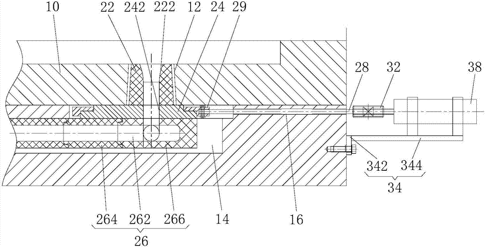
[0047] see figure 1 As shown, the present invention proposes a pouring chassis, which includes a body 10 and a flow control and cutting device. An accommodation cavity 14 is provided inside the body 10 , and flow steel brick holes 12 extending to the upper surface of the body 10 are opened on the body 10 , and the flow steel brick holes 12 communicate with the accommodation cavity 14 .

[0048] The flow control and cutting device includes a flow steel brick 22 , a sliding plate 24 capable of sliding horizontally, a drainage body 26 and a push rod 28 capable of pushing and pulling in the radial direction of the sliding plate 24 . The flow steel brick 22 has a through flow hole 222 , the sliding plate 24


PUM


Abstract

The invention discloses a pouring base plate. The pouring base plate comprises a base plate body and a flow control shutoff device. An accommodating cavity is formed in the base plate body. The base plate body is provided with a runner brick hole which extends to the upper surface of the base plate body and communicates with the accommodating cavity. The flow control shutoff device comprises a runner brick, a sliding plate capable of sliding horizontally, a flow guiding body and a push rod capable of doing push-pull motion; the runner brick is arranged in the runner brick hole; the sliding plate and the flow guiding body are both arranged in the accommodating cavity; the runner brick, the sliding plate and the flow guiding body are sequentially sealed and attached from top to bottom; at least part of the horizontal projection of a lower end opening of a runner hole of the runner brick and at least part of the horizontal projection of an upper end opening of a flow guiding channel of the flow guiding body are overlapped; one end of the push rod is detachably connected with the sliding plate, and the other end of the push rod is located outside the base plate body; and the push rod drives the sliding plate to slide horizontally, and the runner hole and a flow passing hole of the sliding plate can communicate with the flow guiding channel vertically to form a pouring channel. The pouring base plate can control the flow rate and can also shut off the pouring channel, so that a continuous steel column is prevented from being formed.

Description


Claims


Application Information

Patent Timeline
Owner MCC CAPITAL ENGINEERING & RESEARCH
Why Eureka
Try Eureka