Connecting structure between steel column and high-rise truss beam

A technology for connecting structures and truss beams, which is applied in the direction of building construction and construction, can solve the problems of inability to achieve effective fixation and low connection strength of nodes, and achieve the effect of simple installation structure and improved connection strength

Active Publication Date: 2020-04-14
SHANGHAI GREENLAND CONSTR GRP
View PDF10 Cites 0 Cited by
  • Summary
  • Abstract
  • Description
  • Claims
  • Application Information

AI Technical Summary

Problems solved by technology

[0002] In the prefabricated steel structure building, the steel column and the truss beam are fixed by bolts. Although this method can connect and fix the truss beam as a whole, the connection strength of the entire n

Method used


Image

  • Connecting structure between steel column and high-rise truss beam
  • Connecting structure between steel column and high-rise truss beam

Examples


Embodiment Construction

[0013] In order to make the technical means, creative features, goals and effects achieved by the present invention easy to understand, the technical solutions in the embodiments of the present invention will be clearly and completely described below in conjunction with the accompanying drawings in the embodiments of the present invention.

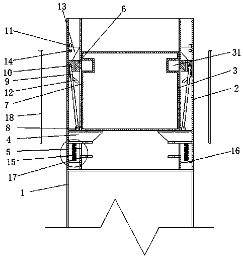
[0014] see Figure 1-2 , this specific embodiment is realized by adopting the following technical scheme, which includes a steel column 1, and the two ends of the upper top surface of the steel column 1 respectively extend vertically upwards to a positioning seat 2, and a positioning seat 2 is arranged between the two positioning seats 2. butt truss beam 3;

[0015] The positioning seat 2 is a hollow square tubular structure as a whole, and an inner armpit beam 4 is arranged inside the positioning seat 2, and one end of the inner armpit beam 4 passes through the inner surface of the positioning seat 2 and extends to two Between the positioni


PUM


Abstract

The invention discloses a connecting structure between a steel column and a high-rise truss beam. The connecting structure comprises the steel column (1), two ends of the upper top surface of the steel column (1) correspondingly extend vertically upwards from positioning seats (2), the truss beam (3) in butt-joint with the positioning seats (2) is arranged between the two positioning seats (2). The positioning seats (2) are of a hollow square tube structure as a whole, inner haunched beams (4) are arranged in the positioning seats (2), one ends of the inner haunched beams (4) penetrate throughthe inner sides of the positioning seats (2) and extend between the two positioning seats (2), and first guide sliding grooves (5) are formed in the inner sides of the positioning seats (2) for the clearance passage of the inner haunched beams (4). According to the connecting structure, the installation structure is simple, and the connection strength between the steel column and the truss beam can be effectively improved.

Description


Claims


Application Information

Patent Timeline
Owner SHANGHAI GREENLAND CONSTR GRP
Why Eureka
Try Eureka