Steel column construction site splicing installation positioner

A locator and steel column technology, which is applied in the direction of construction and building construction, can solve the problems of weak corrosion resistance, labor and materials, etc., and achieve the effects of simplified processing, convenient and accurate installation and positioning, and material saving

Pending Publication Date: 2022-07-15
上海泰大建筑科技有限公司
View PDF0 Cites 0 Cited by
  • Summary
  • Abstract
  • Description
  • Claims
  • Application Information

AI Technical Summary

Benefits of technology

This technology allows for precise placement of an elevated structure such as a tower or building without requiring prewiring beforehand. It involves attaching a device called a holder that holds two columns together with support members at certain positions along its length. By adjusting these supports, it becomes possible to create spaces between them where different parts may have been connected during construction work. Afterward, each part's location will be confirmed through measurements made from this space. Once all necessary connections are completed, there won't require any extra steps like cutting off bolt holes if needed again later when installing other components onto top of the existing one.

Problems solved by technology

This patented method for joining two ends together involves cutting out or painting certain parts beforehand when it're needed. However this process can be time-consuming because each part needs to have its own set of location marks that are used during assembly.

Method used


Image

  • Steel column construction site splicing installation positioner
  • Steel column construction site splicing installation positioner
  • Steel column construction site splicing installation positioner

Examples


Embodiment Construction

[0020] The following description is presented to enable any person skilled in the art to make and use the invention and to integrate it into a specific application context. Various modifications, and various uses in different applications will be readily apparent to those skilled in the art, and the generic principles defined herein may be applied to a wider range of embodiments. Thus, the present invention is not limited to the embodiments set forth herein, but is to be accorded the widest scope consistent with the principles and novel features disclosed herein.

[0021] In the following detailed description, numerous specific details are set forth in order to provide a thorough understanding of the present invention. However, it will be apparent to those skilled in the art that the practice of the present invention may not necessarily be limited to these specific details. In other words, well-known structures and devices are shown in block diagram form without detail in order


PUM


Abstract

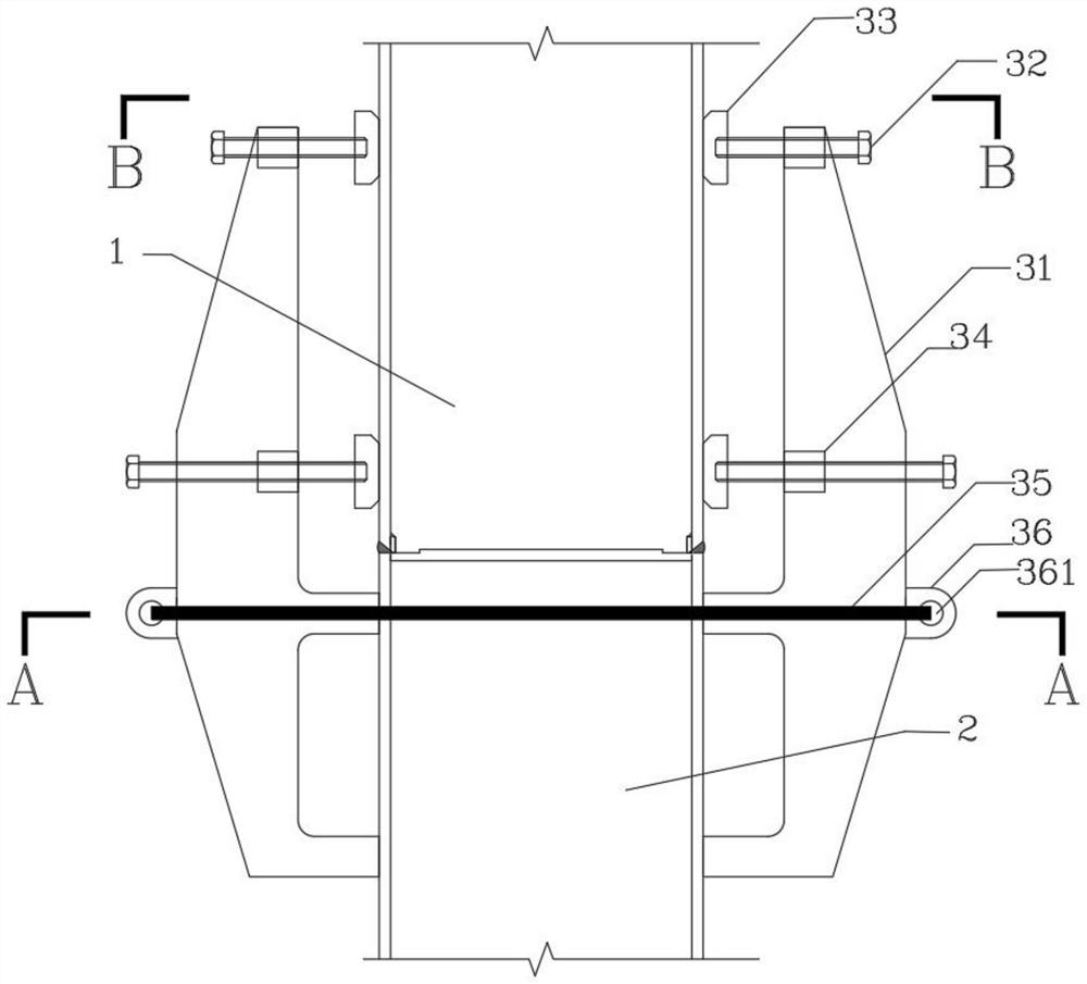
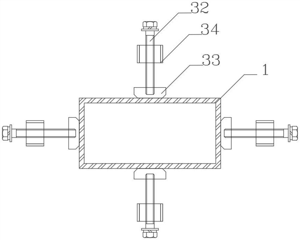
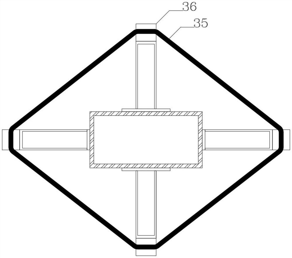
The invention provides a steel column construction site splicing installation positioner which is characterized in that the steel column construction site splicing installation positioner comprises a plurality of positioner bodies 31 arranged at the installation joint of an upper steel column 1 and a lower steel column 2, the plurality of positioner bodies 31 surround the lower steel column 2 and are hooped on the lower steel column 2 through detachable tightening pieces 35, the positioner bodies 31 are further provided with abutting and supporting positioning pieces, and the abutting and supporting positioning pieces are connected with the upper steel column 1 and the lower steel column 2. And the propping positioning pieces on the plurality of positioner main bodies 31 are propped against the upper steel column 1 to position the upper steel column 1.

Description


Claims


Application Information

Patent Timeline
Owner 上海泰大建筑科技有限公司
Why Eureka
Try Eureka