Anastomat switch control assembly, nail cabin assembly rotation control system and control circuit
A technology of switch control and control circuit, applied in surgical fixation nails, medical science, surgery, etc., can solve the problems that the operator cannot perform operations with one hand, the work efficiency is not high, and the patient's burden is heavy, so as to achieve low cost and space saving. , the effect of convenient operation
- Summary
- Abstract
- Description
- Claims
- Application Information
AI Technical Summary
Benefits of technology
Problems solved by technology
Method used
Image

Examples
Embodiment 1
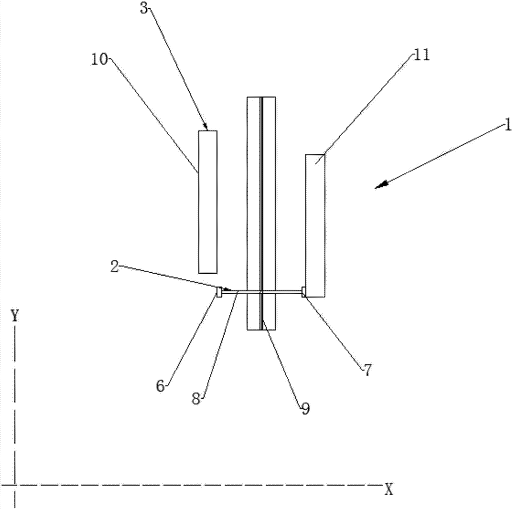
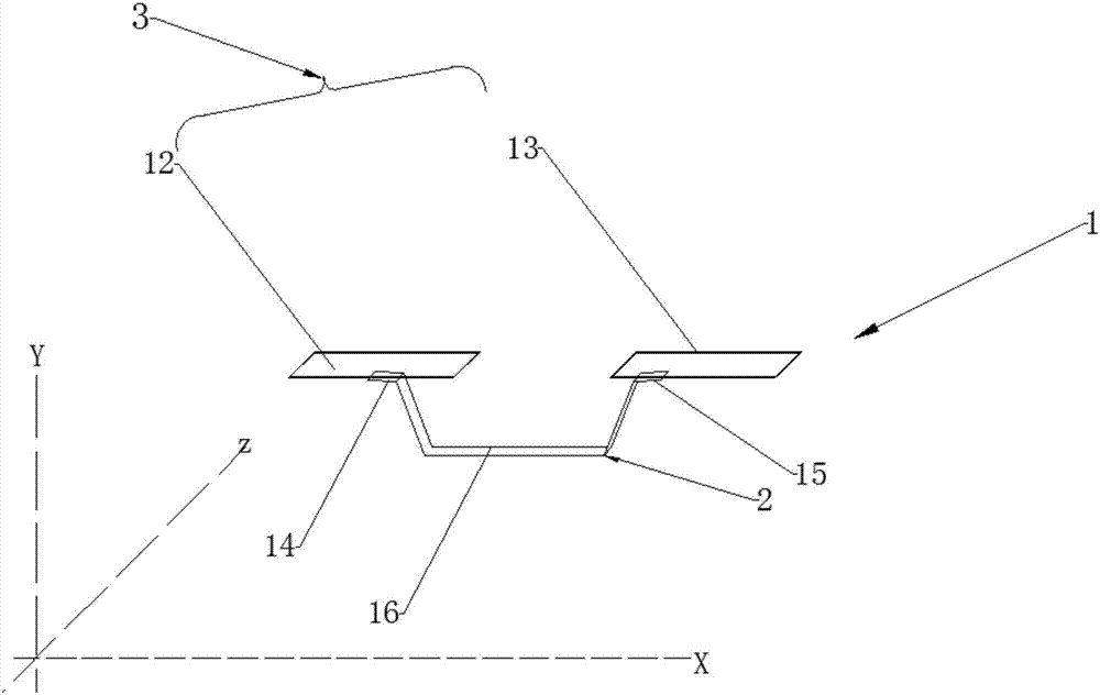
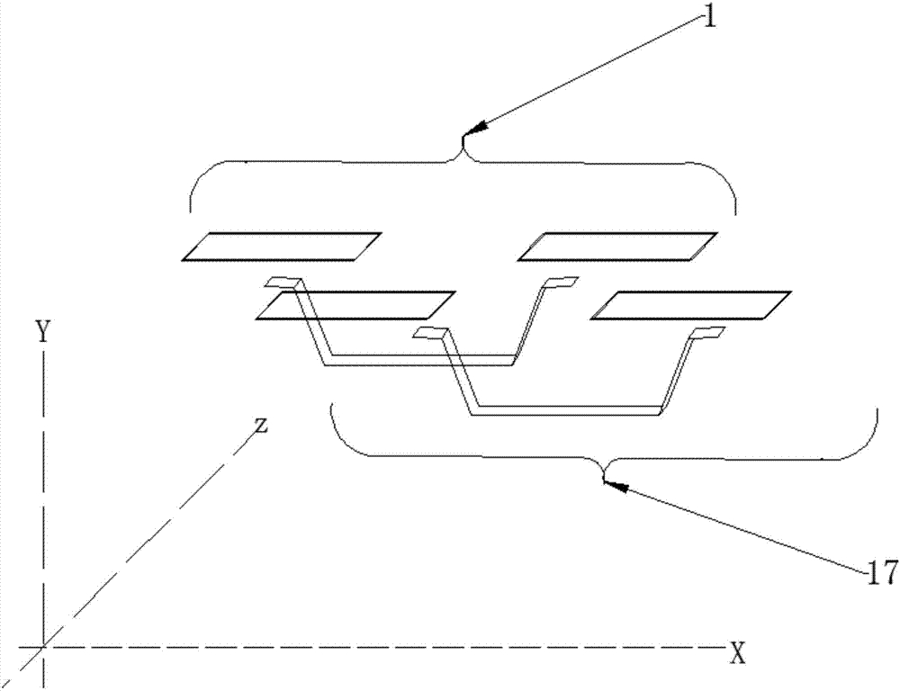
[0038] This embodiment provides a stapler switch control assembly, the switch control assembly includes a first switch movement trigger pin 2 and a fixed trigger pin 3; the fixed trigger pin 3 is fixed in the stapler, and is provided with At least two travel limit parts; the motion trigger pin 2 moves relative to the fixed trigger pin 3, and the motion trigger pin 2 is provided with at least two moving conductive parts, and at least two of the moving conductive parts electrical connection between them; when the motion trigger pin 2 is moving relative to the fixed trigger pin 3, at least two of the moving conductive parts are engaged or not engaged with at least two of the travel limit parts during the movement process The positional relationship is controlled by moving to control the length of the engagement time so as to control the conduction time of at least two stroke limiters.
[0039] Let’s take two moving conductive parts as an example for illustration. Because the two mov
Embodiment 2
[0048] This embodiment provides a stapler cartridge assembly rotation control system, including the switch control assembly described in Embodiment 1, a power slider 30 and a circuit board 31; the fixed trigger pin 3 of the switch control assembly is set on On the circuit board 31, the motion trigger pin 2 of the switch control assembly is arranged on the power slider 30, and the stapler cartridge assembly is detachably arranged on the stapler body, and is detachably mounted on the stapler body. The power supply slider 30 is pushed.
[0049]In order to meet the different needs of the operation, the staple cartridge assembly of the stapler includes a staple cartridge assembly that can rotate left and right (hereinafter referred to as a rotating head staple cartridge assembly), and a staple cartridge assembly that cannot rotate left and right (hereinafter referred to as a straight head rotating assembly); The embodiments are described with the rotating head nail cartridge assembly
Embodiment 3
[0051] This embodiment provides a stapler control circuit, including a power supply, the switch control assembly described in Embodiment 1 or 2 above, a control circuit, and a DC motor; the power supply supplies power, and the stapler is applied by the rotation of the DC motor. Driving force: the switch control component cooperates with the control circuit to control the movement of the DC motor to perform power-off, power-on, rotation amount, forward rotation, reverse rotation, forward rotation braking and reverse braking. This control circuit replaces the MCU control circuit system in the all-electric intelligent endoscopic stapler, which solves the problems of high equipment cost and heavy burden on patients, and also solves the problem that the operation of the semi-electric endoscopic stapler needs to rely on manual control. steps, the work efficiency is not high, and the operator cannot perform the operation with one hand. Through the complete control of the circuit, the op
PUM
 Abstract
Description
Claims
Application Information
 - R&D Engineer
- R&D Manager
- IP Professional
- Industry Leading Data Capabilities
- Powerful AI technology
- Patent DNA Extraction
Browse by: Latest US Patents, China's latest patents, Technical Efficacy Thesaurus, Application Domain, Technology Topic.
© 2024 PatSnap. All rights reserved.Legal|Privacy policy|Modern Slavery Act Transparency Statement|Sitemap