Static mixer and mixing device

A static mixer and spacer technology, applied in fluid mixers, mixers, transportation and packaging, etc., can solve problems such as inflexibility, complicated static mixer structure design, and small application range of a single static mixer, and achieve Effects for improved performance, good mixing effects

Active Publication Date: 2017-07-07
SUZHOU NAPO ADVANCED MATERIAL TECH CO LTD
View PDF4 Cites 1 Cited by
  • Summary
  • Abstract
  • Description
  • Claims
  • Application Information

AI Technical Summary

Problems solved by technology

[0004] Based on this, it is necessary to provide a static mixer with a simple structural design, flexibility and a wide range of applications in view

Method used


Image

  • Static mixer and mixing device
  • Static mixer and mixing device
  • Static mixer and mixing device

Examples


Embodiment Construction

[0024] In order to make the object, technical solution and advantages of the present invention clearer, the present invention will be further described in detail below in conjunction with specific embodiments. It should be understood that the specific embodiments described here are only used to explain the present invention, and are not intended to limit the present invention.

[0025] Unless otherwise defined, all technical and scientific terms used herein have the same meaning as commonly understood by one of ordinary skill in the technical field of the invention. The terminology used herein in the description of the present invention is only for the purpose of describing specific embodiments, and is not intended to limit the present invention. As used herein, the term "and / or" includes any and all combinations of one or more of the associated listed items.

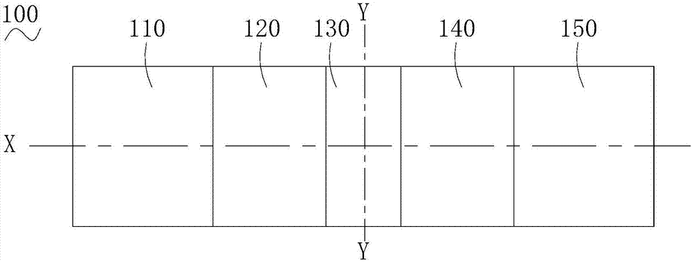
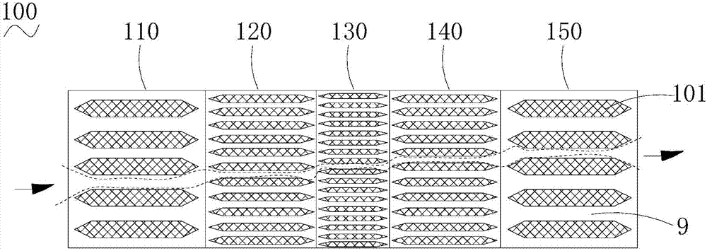
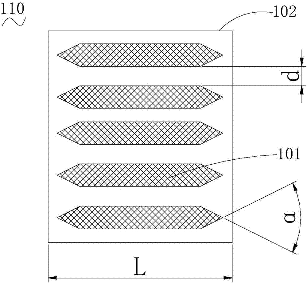
[0026] see Figure 1-3 , the static mixer 100 according to an embodiment of the present invention includes several s


PUM

PropertyMeasurementUnit
Spacingaaaaaaaaaa
Angleaaaaaaaaaa

Abstract

The invention relates to a static mixer which is in a column shape. The static mixer comprises a plurality of flow division sections which are arranged axially. A plurality of flow channels penetrating through the flow division sections are formed in the flow division sections. The number of the flow channels in one flow division section is different from that of the flow channels in the adjacent flow division section. According to the static mixer, the number of the flow channels in one flow division section is different from that of the flow channels in the adjacent flow division section, and the flow channels of the adjacent flow division sections are staggered; the widths of the flow channels change, fluids are subjected to a series of cutting, stretching and folding when flowing through the different flow division sections, so that the fluids are fully mixed. According to the static mixer, the flow division sections are simple in structural design. The static mixer can adapt to mixing of viscous fluids and low-viscosity fluids, and is wide in application range. The invention further provides a mixing device.

Description


Claims


Application Information

Patent Timeline
Owner SUZHOU NAPO ADVANCED MATERIAL TECH CO LTD
Why Eureka
Try Eureka