Coating mixer

A technology for mixers and paints, applied in mixers, mixers with rotating stirring devices, dissolving, etc., can solve the problems of inconvenient mixing of paints, time wasting, complicated operation, etc., and achieve saving mixing time, convenient use, and fast The effect of mixing and stirring

Inactive Publication Date: 2017-08-11
WUXI VOCATIONAL & TECHN COLLEGE
View PDF2 Cites 3 Cited by
  • Summary
  • Abstract
  • Description
  • Claims
  • Application Information

AI Technical Summary

Benefits of technology

The technical effect that this new device helps mix quickly while still being easy-to-use for users who don't have any special tools or equipment needed at all times.

Problems solved by technology

Technological Problem: In this patented technical problem addressed in this patents, there exist various ways for constructors to create decorative houses or shelves without having excessive room inside these constructions due to its complexity and lack of balance between interior design elements like timber frames, lumber members, stiles, wires/posts, and other components. Existing paints have limitations in mixing, wastefulness during construction, slow-down operations, complex manipulation, and unnecessary material consumption.

Method used


Image

  • Coating mixer

Examples


Embodiment Construction

[0014] In order to make the object, technical solution and advantages of the present invention clearer, the present invention is described below through specific embodiments shown in the accompanying drawings. It should be understood, however, that these descriptions are exemplary only and are not intended to limit the scope of the present invention. Also, in the following description, descriptions of well-known structures and techniques are omitted to avoid unnecessarily obscuring the concept of the present invention.

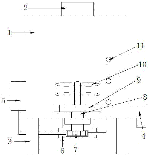
[0015] Such as figure 1 As shown, this specific embodiment adopts the following technical solutions: it includes a casing 1, a liquid inlet pipe 2, a support foot 3, a liquid outlet pipe 4, an air pump 5, an air flow chamber 6, a wind impeller 7, a rotating shaft 8, a mixing impeller 9, Stirring blade 10, gas mixing nozzle 11; support feet 3 are installed on the bottom of the box body 1, a liquid inlet pipe 2 is installed on the upper end of the box body 1, and


PUM


Abstract

The invention discloses a coating mixer, and relates to the technical field of construction. According to the coating mixer, support legs are installed at the bottom of a box, a liquid inlet pipe is installed at the upper end of the box, a liquid outlet pipe is installed at the right lower end of the box, a gas pump is installed on the left side wall of the box, a rotating shaft is installed at the bottom of the box through a bearing base, the upper end of the rotating shaft is connected with the bottom of the box in a penetrating mode, a mixed impeller is installed at the upper end of the rotating shaft, multiple stirring blades are installed at the upper end of the mixed impeller through connecting rods, a gas flow bin is installed at the bottom of the box, the lower end of the rotating shaft is connected with a gas flow groove of the gas flow bin in penetrating mode, a wind impeller is installed at the lower end of the rotating shaft, the wind impeller is arranged in the gas flow groove, the gas pump is connected with the gas inlet of the gas flow groove of the gas flow bin through a gas pipe, and the gas outlet of the gas flow groove is connected with multiple mixed gas nozzles which are installed on the box separately; the coating mixer is conductive to achieving quick mixing and stirring and convenient to use and operate, and can save the mixing time.

Description


Claims


Application Information

Patent Timeline
Owner WUXI VOCATIONAL & TECHN COLLEGE
Why Eureka
Try Eureka