Mass-flow-meter calibration detection device

A mass flow meter and detection device technology, applied in the detection field, can solve the problem of no constant current voltage stabilizer, etc., and achieve the effects of improving product calibration accuracy, measurement accuracy, and calibration measurement accuracy.

Pending Publication Date: 2017-09-08
CHONGQING CHUANYI AUTOMATION
View PDF5 Cites 2 Cited by
  • Summary
  • Abstract
  • Description
  • Claims
  • Application Information

AI Technical Summary

Problems solved by technology

[0002] The mass flowmeter is a flow measuring instrument for measuring the mass flow in the pipeline. The existing mass flowmeter calibration pipeline, whether it is the calibration of the mass flow or the calibration of the density, adopts the method of straight calibration pipeline, and the mass flowmeter There is no constant current and voltage stabilizing device at the front end of the flowmeter calibration flange

Method used


Image

  • Mass-flow-meter calibration detection device
  • Mass-flow-meter calibration detection device
  • Mass-flow-meter calibration detection device

Examples


Example Embodiment

[0016] The following describes the implementation of the present invention through specific specific examples. Those skilled in the art can easily understand other advantages and effects of the present invention from the content disclosed in this specification. The present invention can also be implemented or applied through other different specific embodiments, and various details in this specification can also be modified or changed based on different viewpoints and applications without departing from the spirit of the present invention. It should be noted that the following embodiments and the features in the embodiments can be combined with each other if there is no conflict.

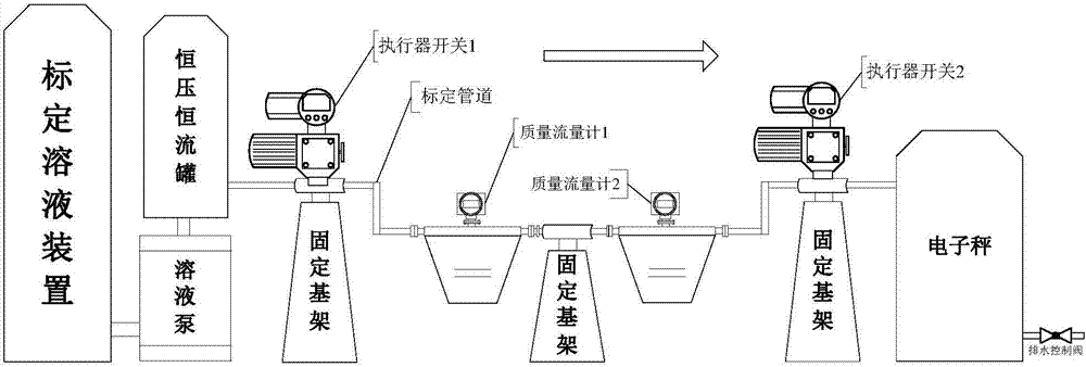
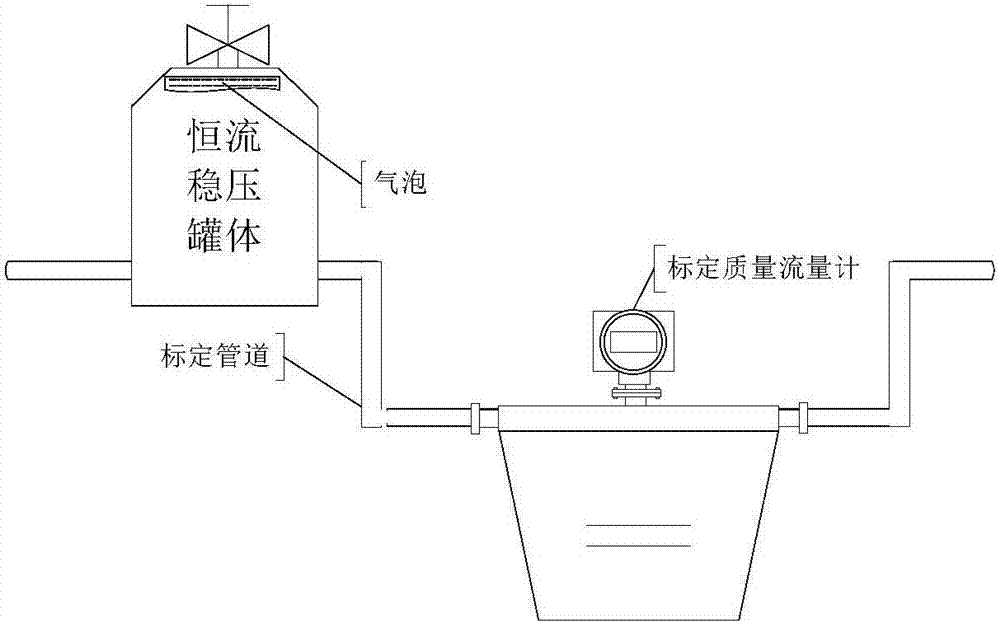
[0017] It should be noted that the illustrations provided in the following embodiments only illustrate the basic idea of ​​the present invention in a schematic manner. The figures only show the components related to the present invention instead of the number, shape, and number of components in actual impl


PUM


Abstract

The invention provides a mass-flow-meter calibration detection device. The mass-flow-meter calibration detection device comprises a calibration solution output unit, a calibration pipe, a metering unit and fixing base frames for fixing the calibration pipe. The calibration solution output unit is connected with the calibration pipe, and the calibration pipe is connected with the metering unit. According to the mass-flow-meter calibration detection device, a constant-current stable-voltage tank is arranged at the front end of a calibration mass flow meter, and can provide a constant-current stable-voltage calibration medium solution, it is achieved that mass flow meters can output stable phase difference signals in the calibration metering process, and meanwhile the calibration mass flow meter is installed at a U-shaped pipe and calibrated; the calibration metering accuracy of mass-flow-meter products can be increased, the metering accuracy of a whole calibration device system can also be increased, and the defect that the calibration accuracy of a product cannot be increased through an existing calibration device is overcome.

Description


Claims


Application Information

Patent Timeline
Owner CHONGQING CHUANYI AUTOMATION
Why Eureka
Try Eureka