Plug-in type ultrasonic flow meter, flow metering system and method
An ultrasonic and plug-in technology, applied in the direction of measuring flow/mass flow, liquid/fluid solid measurement, measuring devices, etc., can solve the problems of affecting the measurement results and the zero point cannot be accurately determined, so as to achieve high transmission quality and realize accurate measurement , the effect of structural stability
- Summary
- Abstract
- Description
- Claims
- Application Information
AI Technical Summary
Benefits of technology
Problems solved by technology
Method used
Image

Examples
no. 1 example
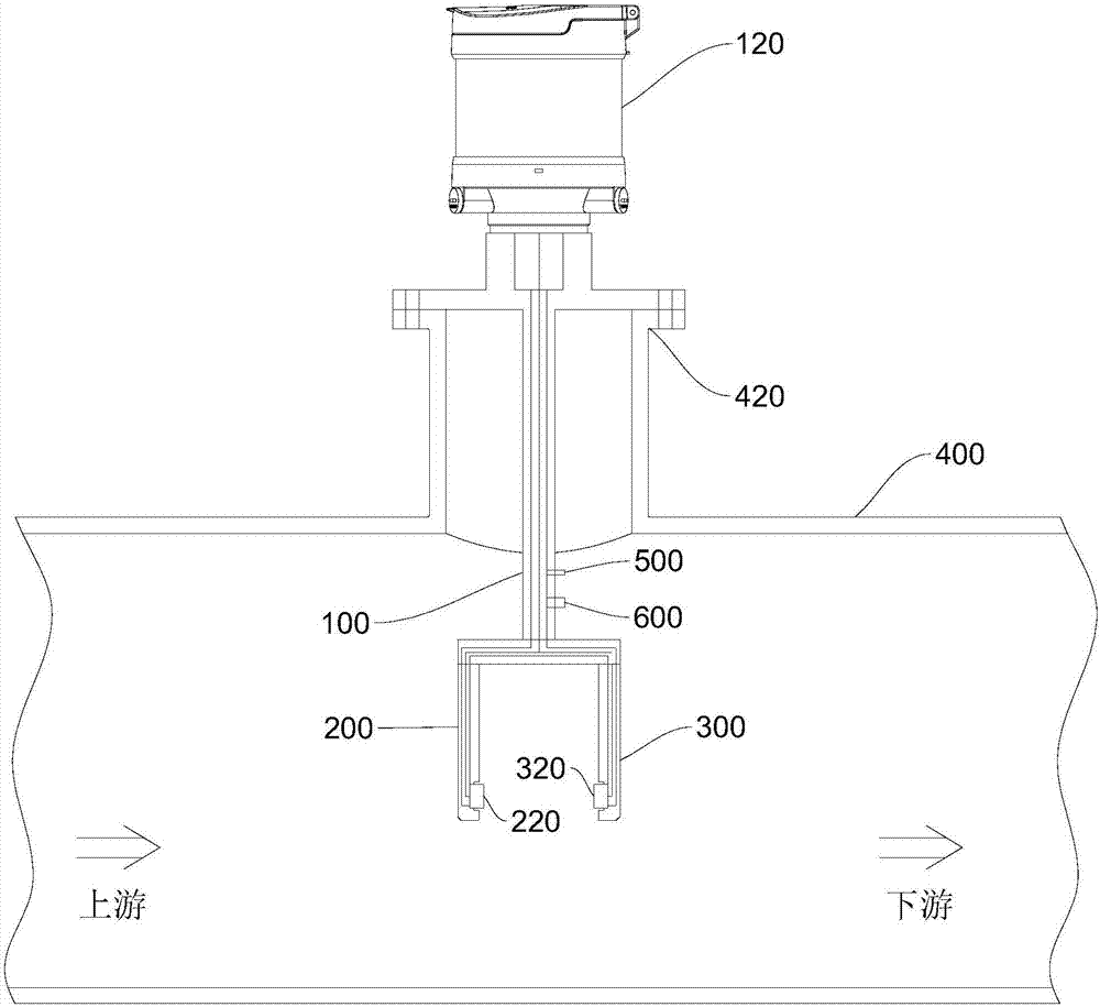
[0042] Please refer to figure 1 , this embodiment provides an insertion type ultrasonic flowmeter, which is applied to the pipeline 400 . The insertion type ultrasonic flowmeter includes a main plunger 100 and a gauge head 120 . One end of the main plunger 100 on the outside of the pipe 400 is connected to the meter head 120, and the end of the main plunger 100 inserted into the pipe 400 has a first branch portion 200 and a second branch portion symmetrically arranged at intervals. The branch part 300, the first branch part 200 and the second branch part 300 are respectively arranged upstream and downstream of the pipeline 400, the first branch part 200 is provided with a first ultrasonic transducer 220, so A second ultrasonic transducer 320 corresponding to the position of the first ultrasonic transducer 220 is disposed on the second branch portion 300 . In this embodiment, the connecting line between the first ultrasonic transducer 220 and the second ultrasonic transducer 320
no. 2 example
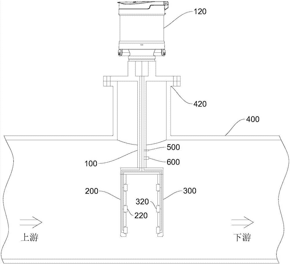
[0063] Please refer to image 3 , this embodiment provides an insertion type ultrasonic flowmeter, the biggest difference from the first embodiment of the present invention is that, in this embodiment, the first branch part 200 in the insertion type ultrasonic flowmeter is inside the pipeline 400 A plurality of ultrasonic transducers are also arranged at different heights, and a plurality of ultrasonic transducers with the same number and corresponding positions as the plurality of ultrasonic transducers on the first branch 200 are also arranged on the second branch part 300 . energy device. An ultrasonic sound channel is formed between every two ultrasonic transducers corresponding to the positions on the first branch part 200 and the second branch part 300 , and the straight line where each ultrasonic sound channel is located is parallel to the central axis of the pipeline 400 .
[0064] In this embodiment, in order to correspond to the multi-channel plug-in ultrasonic flowme
no. 3 example
[0067] Please refer to Figure 4 , this embodiment provides an insertion type ultrasonic flowmeter, and the biggest difference from the first embodiment of the present invention is that in this embodiment, the first branch part 200 in the insertion type ultrasonic flowmeter is provided with a An ultrasonic transducer 220 is located at the first acoustic reflector 240 at different heights. On the other hand, the second branch portion 300 is also provided with a second acoustic reflector 240 at the same height as the first acoustic reflector 240 on the first branch portion 200. The reflecting mirror 340 , the connecting line between the first acoustic reflecting mirror 240 and the second acoustic reflecting mirror 340 are located in the same plane as the central axis of the pipe 400 .
[0068] Preferably, in this embodiment, the first ultrasonic transducer 220 and the second ultrasonic transducer 320 can be arranged at the same height, that is, the connection line between the first
PUM
 Abstract
Description
Claims
Application Information
 - R&D Engineer
- R&D Manager
- IP Professional
- Industry Leading Data Capabilities
- Powerful AI technology
- Patent DNA Extraction
Browse by: Latest US Patents, China's latest patents, Technical Efficacy Thesaurus, Application Domain, Technology Topic.
© 2024 PatSnap. All rights reserved.Legal|Privacy policy|Modern Slavery Act Transparency Statement|Sitemap