Low Pressure Transducer Using Beam and Diaphragm

a low-pressure transducer and beam technology, applied in the field of fluid pressure sensors, can solve the problems of high strain level, affecting both sensitivity and accuracy, and metal diaphragms showing undesirable interactions

Inactive Publication Date: 2009-08-27
MEASUREMENT SPEC
View PDF13 Cites 5 Cited by
  • Summary
  • Abstract
  • Description
  • Claims
  • Application Information

AI Technical Summary

Benefits of technology

The inventor describes two ways how it can measure pressures accurately with a small device called a liquid sensor. One way involves attaching a special material like quartz crystal onto certain parts of the device's sensors. This allows them to monitor changes caused by different levels of pressure over time. Another approach uses a separate mechanism attached between the main part of the sensor itself and its operating environment (the rest). By measuring these signals, we aim to provide technical means for improving the accuracy and reliability of such measurements.

Problems solved by technology

The technical problem addressed in this patented text relates to reducing variations in measurement results when measuring very small changes on different types of material that can cause errors due to differences in their coefficient of thermal expansions.

Method used


Image

  • Low Pressure Transducer Using Beam and Diaphragm
  • Low Pressure Transducer Using Beam and Diaphragm
  • Low Pressure Transducer Using Beam and Diaphragm

Examples


Embodiment Construction

[0016]It is to be understood that the figures and descriptions of the present invention have been simplified to illustrate elements that are relevant for a clear understanding of the present invention, while eliminating, for purposes of clarity, many other elements found in typical pressure sensing methods and systems. However, because such elements are well known in the art, and because they do not facilitate a better understanding of the present invention, a discussion of such elements is not provided herein. The disclosure herein is directed to all such variations and modifications known to those skilled in the art.

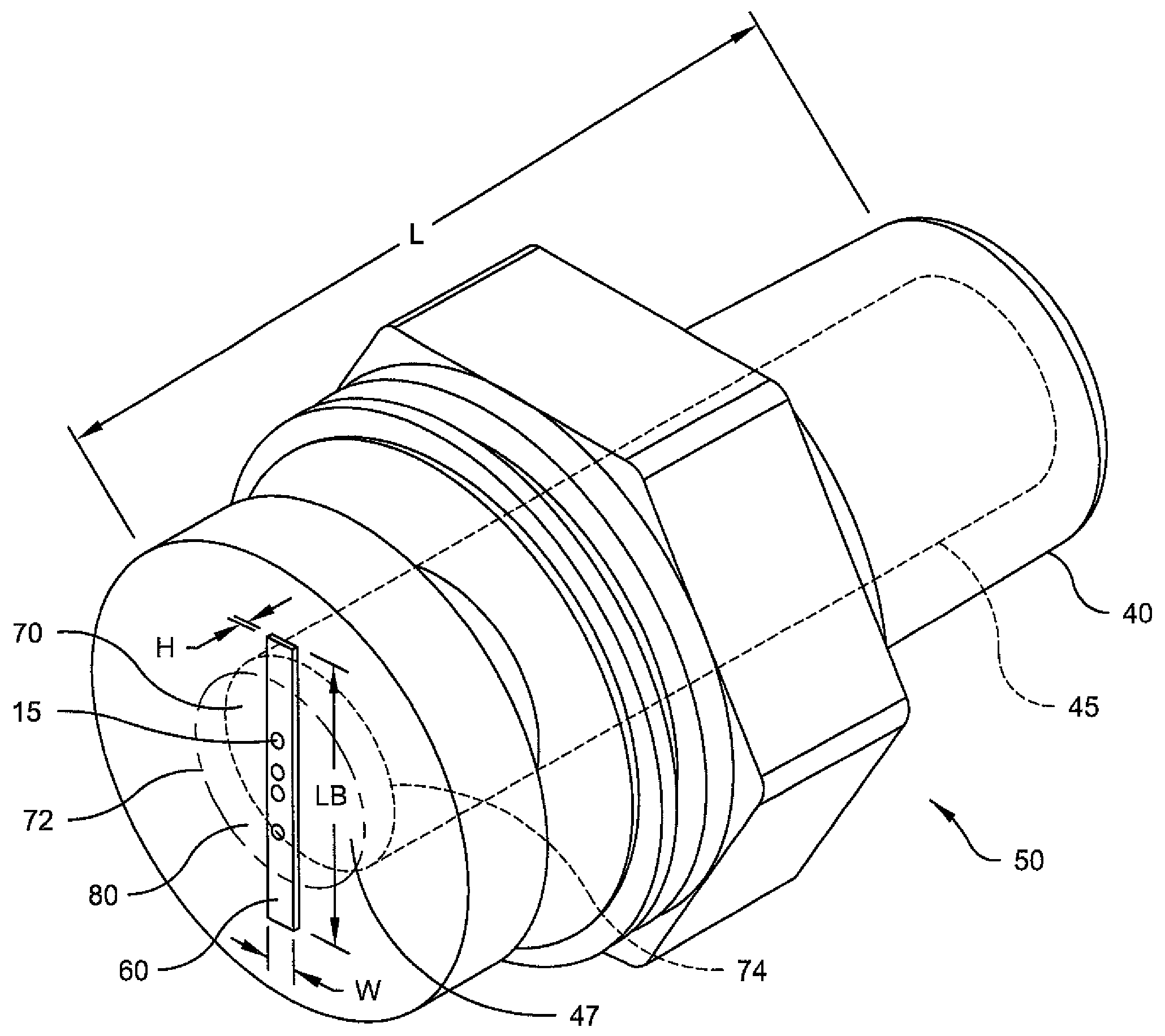
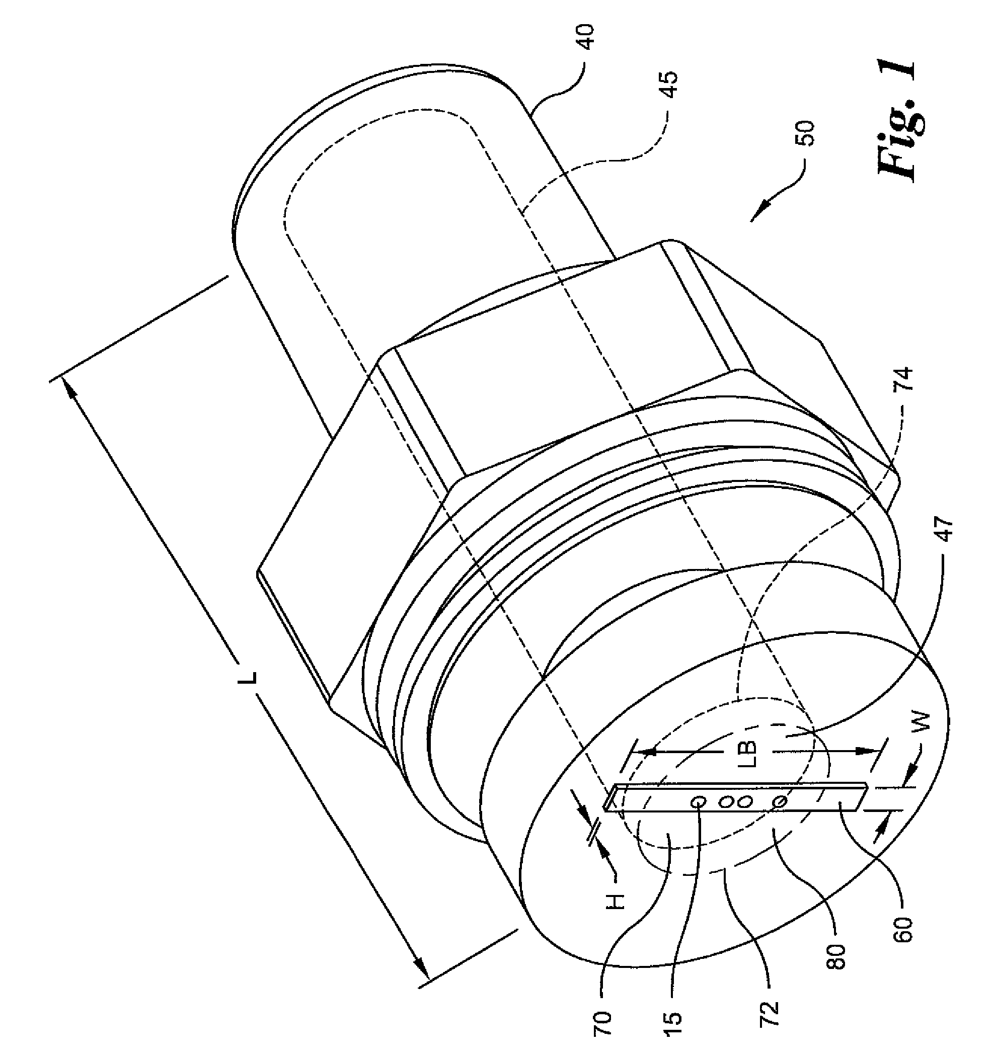
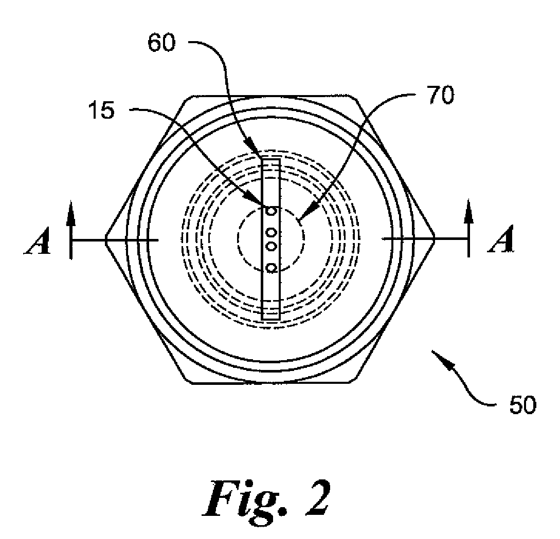
[0017]The present invention relates to a low pressure metal transducer that utilizes silicon strain gages glass bonded to a raised metal surface also referred to as a cross beam, which is formed from metal stock integral to a metal diaphragm formed from a cylindrical section. The ratio of the area of diaphragm top surface embodying the metal beam to the total area of the


PUM

PropertyMeasurementUnit
Thicknessaaaaaaaaaa
Thicknessaaaaaaaaaa
Thicknessaaaaaaaaaa

Abstract

A low-pressure transducer including a disc-shaped metal diaphragm to which a fluid pressure is applied, wherein the diaphragm contains a raised beam formed by thinning the entire exterior surface of the diaphragm except for the beam; and at least one silicon strain gage glass bonded to the beam, wherein the low-pressure transducer can accurately gage pressures at least as low as 15 psi. The present invention also comprises a method for manufacturing a pressure transducer including the steps of forming a cylindrical diaphragm having a top surface and a lower surface; establishing a diameter and a thickness of the diaphragm relative to an operational plane by a creating a hole axially through the transducer body that terminates at the lower surface; and creating a raised surface in the shape of a cross beam integral to the operational surface; and bonding one or more strain gages thereupon.

Description


Claims


Application Information

Patent Timeline
Owner MEASUREMENT SPEC
Why Eureka
Try Eureka