Manufacturing method of rudder blade jig frame

A manufacturing method and technology of rudder blades, which are applied in the manufacture of tools, welding equipment, metal processing, etc., can solve the problems of narrow tire frame operation space, small size of rudder blades, and difficult construction, so as to reduce construction difficulty and increase operation space , the effect of strengthening control

Active Publication Date: 2017-09-29
CSSC HUANGPU WENCHONG SHIPBUILDING COMPANY
View PDF6 Cites 0 Cited by
  • Summary
  • Abstract
  • Description
  • Claims
  • Application Information

AI Technical Summary

Benefits of technology

In this new technology, there's an improved way that allows for easier assembly or maintenance on small vehicles by creating separate parts called blades instead of just one large part like traditional wheels used during driving. These smaller components can be easily installed onto different types of vehicle designs without compromising their performance. Overall, these improvements make the design process more efficient and reliable while maintaining high quality standards over time.

Problems solved by technology

The technical problem addressed by this patented technology relates to improving the efficiency at producing highly precise rudders used in vehicles such as boats or cars without sacrificing their durability during use. Specifically, current methods require expensive tools like lasers or machine tool machines (LM) to create these types of structures accurately while also reducing labor costs associated therewith.

Method used


Image

  • Manufacturing method of rudder blade jig frame
  • Manufacturing method of rudder blade jig frame
  • Manufacturing method of rudder blade jig frame

Examples


Embodiment Construction

[0024] The following will clearly and completely describe the technical solutions in the embodiments of the present invention with reference to the accompanying drawings in the embodiments of the present invention. Obviously, the described embodiments are only some, not all, embodiments of the present invention. Based on the embodiments of the present invention, all other embodiments obtained by persons of ordinary skill in the art without creative efforts fall within the protection scope of the present invention.

[0025] In a preferred embodiment of the present invention, a method for manufacturing a rudder blade tire frame includes the following steps:

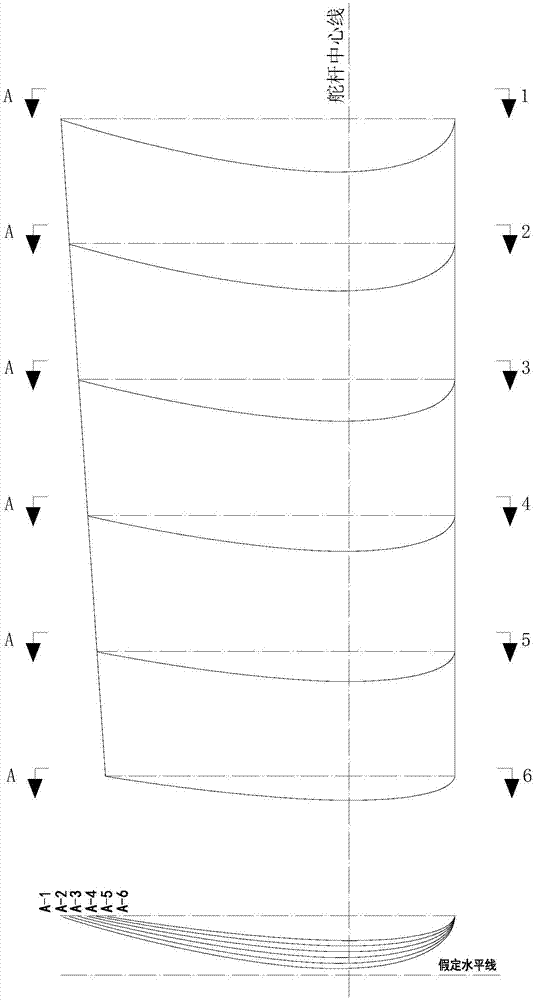
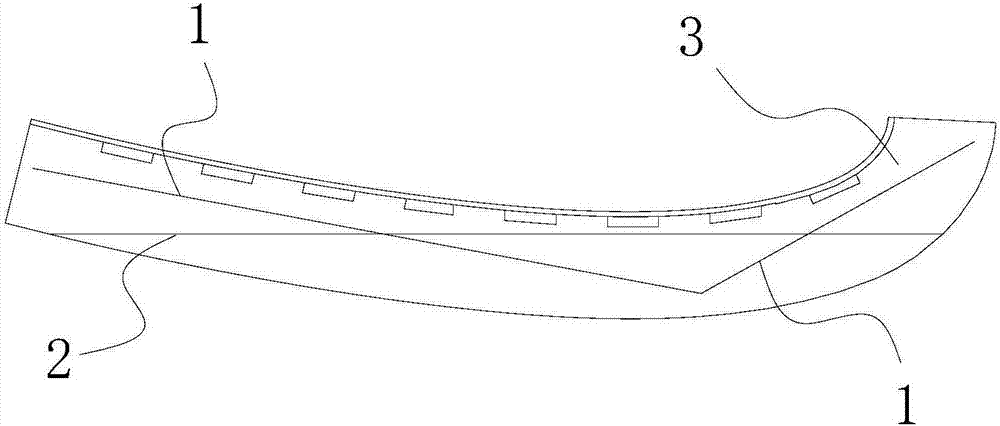
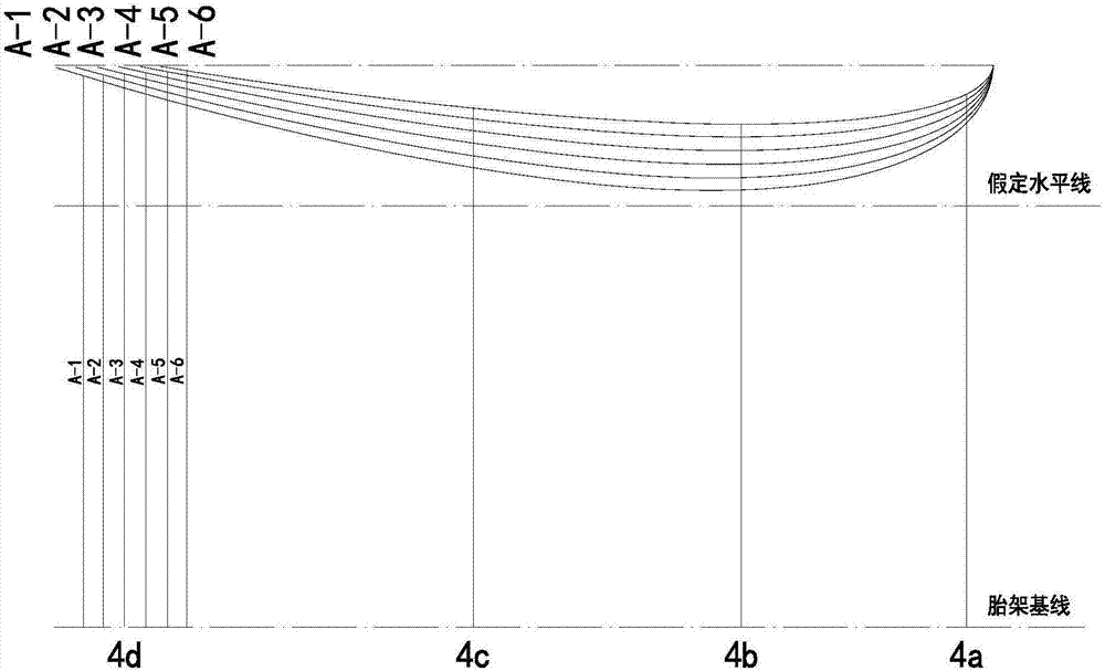
[0026] Step one, such as Figure 1 to Figure 3 As shown, taking the side of the rudder blade in contact with the tire frame as the object, divide the rudder blade into A-1 crosspiece to A-6 crosspiece along the direction of the centerline of the rudder stock, and obtain the transverse profile diagram of the rudder blade. Draw


PUM


Abstract

The invention provides a manufacturing method of a rudder blade jig frame. The manufacturing method comprises the following steps that firstly, a jig frame template is manufactured through cutting; secondly, the jig frame template is checked with a transverse profile drawing of a rudder blade as the reference, and vertical columns are welded to the qualified jig frame template according to a vertical column distribution profile drawing, so that a plurality of crosspiece jig mould frame bodies are formed; and thirdly, the crosspiece jig mould frame bodies are arranged and welded to form the rudder blade jig frame. According to the method, the precision of the jig frame can be improved, and meanwhile the manufacturing difficulty of the jig frame is lowered.

Description


Claims


Application Information

Patent Timeline
Owner CSSC HUANGPU WENCHONG SHIPBUILDING COMPANY
Why Eureka
Try Eureka