Magnetic force power apparatus

A power device and magnetic technology, applied in the direction of electromechanical devices, electrical components, etc., can solve the problems of complex structure, difficult magnetization of magnetic power machines, etc., and achieve the effects of convenient operation, convenient magnetization maintenance, and long service life

Inactive Publication Date: 2017-11-21
陆剑峰
View PDF0 Cites 0 Cited by
  • Summary
  • Abstract
  • Description
  • Claims
  • Application Information

AI Technical Summary

Benefits of technology

This technology has several benefits that make it easier to produce with ease compared to existing methods like iron powder or magnetic materials used today. It also lasts longer over time without losing its effectiveness due to factors such as wear out caused by repeated usage.

Problems solved by technology

In this patented technical problem addressed in this patents relates to improving permanence-motion machines used at high speeds over time due to factors like wear out and tearage. These machines cannot continue moving because they lose some amount of energy when stopped suddenly.

Method used


Image

  • Magnetic force power apparatus
  • Magnetic force power apparatus

Examples


Embodiment Construction

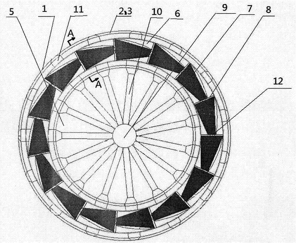
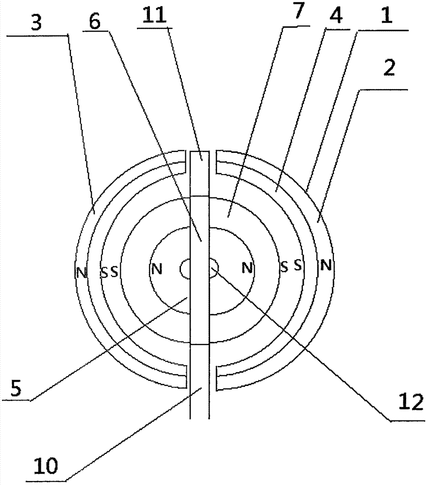
[0027] Attached below figure 1 , attached figure 2 The present invention is further described:

[0028] A kind of magnetic power device, it comprises: stator 1, rotor 5, described stator 1 comprises mutually symmetrically arranged front semicircle-arc slot shell 2, rear semi-arc slot shell 3, described front semi-circle arc slot shell 2. More than two semicircle-arc permanent magnets 4 are successively fixed in the groove shell of the rear semicircle-arc groove shell 3. Shaped groove shell 3 is arranged in cooperation; Described rotor 5 comprises an annular ring plate 6, and described annular ring plate 6 is arranged in the stator 1, and the front and back of described annular ring plate 6 are respectively More than three semiconical permanent magnets 7 are arranged successively, and the described semicircular arc permanent magnet 4 and the semiconical permanent magnet 7 are disassembled and arranged in polarity, and between the described adjacent two semiconical magnets 7 A


PUM


Abstract

The invention discloses a magnetic power device, which comprises: a stator, a rotor, and the stator includes a front semi-arc slot shell, a rear semi-arc slot shell, a front semi-arc slot shell, and a rear semi-arc slot shell arranged symmetrically. Two or more semi-arc-shaped permanent magnets are respectively fixed in sequence in the slot shell, and the semi-arc-shaped permanent magnets are arranged in cooperation with the front semi-arc-shaped slot shell and the rear semi-arc-shaped slot shell; the rotor includes a circular ring plate , the annular ring plate is arranged in the stator, and the front and back of the annular ring plate are respectively provided with more than three semi-conical permanent magnets in sequence, and the semi-arc permanent magnets and the semi-conical permanent magnets are in phase It has the advantages of simple structure, easy manufacture, convenient operation, long service life, convenient magnetization and maintenance, and is more suitable for popularization and use.

Description


Claims


Application Information

Patent Timeline
Owner 陆剑峰
Why Eureka
Try Eureka