Connection device and lifting mechanism

A technology of connecting device and lifting shaft, which is applied in the directions of conveyor objects, transportation and packaging, electrical components, etc., can solve the problem of the maximum height of the lifting shaft being not adjustable, and achieve the effect of improving the versatility

Active Publication Date: 2017-12-12
BEIJING NAURA MICROELECTRONICS EQUIP CO LTD
View PDF6 Cites 0 Cited by
  • Summary
  • Abstract
  • Description
  • Claims
  • Application Information

AI Technical Summary

Benefits of technology

This patented technology allows for flexible adjustment of the lift-shaft excursions by allowing connections at both ends of each component without requiring excessive force from bolts. By inserting holes along one side of the assembly's main body, it becomes possible to make changes such as adding more bushings or changing the shape of the support surface around which they run. Additionally, there may also include features like temperature control during processing. Overall, these technical improvements allow for better performance and functionality when utilizing various heating systems.

Problems solved by technology

This patented technology describes two main issues related to current methods of lifting mechanisms during semiconductor fabrication processes such as deposition chambrophy etches and cleanings. These techniques involve adjustment of the elevating movement based upon factors like temperature, pressure, etc., but they have limitations due to variations caused by component dimensions and placement accuracy. Additionally, these systems require multiple tools to set up each stage separately, leading to increased downtime time and potential failures.

Method used


Image

  • Connection device and lifting mechanism
  • Connection device and lifting mechanism
  • Connection device and lifting mechanism

Examples


Embodiment Construction

[0039] The technical solutions in the present invention will be clearly and completely described below with reference to the accompanying drawings of the present invention. Obviously, the described embodiments are a part of the embodiments of the present invention, not all of the embodiments. Based on the embodiments of the present invention, all other embodiments obtained by those of ordinary skill in the art without creative work fall within the protection scope of the present invention.

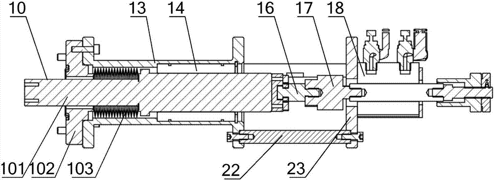
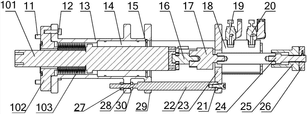
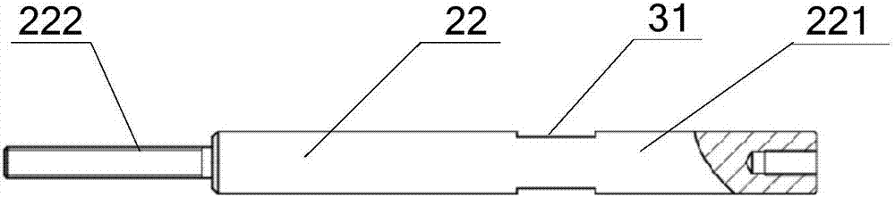
[0040] By improving the structure and connection of the connecting column and the linear bearing sleeve, the invention realizes that the use length of the connecting column can be flexibly adjusted, can overcome the errors introduced by the processing and assembly of parts, and realize the pick-and-place process position and the degassing or annealing process position. accurate positioning, and can be used with different types of heating components to improve the extensive use.

[0041] Combi


PUM


Abstract

The invention provides a connection device and a lifting mechanism. A first through hole is formed in a first flange of a linear bearing sleeve, a second end of a connection vertical post penetrates through the first through hole and is in clearance fit with the first through hole, the second end of the connection vertical post is tightly connected with the first flange by a fastening piece, so that the length of the connection vertical post actually having a connection effect can be flexibly adjusted, and the maximum height of a lifting shaft extending to a process cavity chamber is flexibly adjusted; the distance between the linear bearing sleeve and an air cylinder installation plate is adjusted with regard to part processing and installation errors, so that the maximum height of the lifting shaft extending to the cavity chamber is ensured, and a wafer taking/placing process station and a degassing or annealing process station is accurately positioned; and the distance between the linear bearing sleeve and the air cylinder installation plate also can be flexibly adjusted within a certain range according to the size of a heating part, and the application universality is improved.

Description


Claims


Application Information

Patent Timeline
Owner BEIJING NAURA MICROELECTRONICS EQUIP CO LTD
Why Eureka
Try Eureka