Door hinge fixing plate connecting structure

A technology for connecting structure and fixing plate, applied in the direction of folding plate, door/window fittings, building structure, etc., can solve the problem of door hinge fixing screw holes being easily damaged, and achieves easy falling off, simple installation, and guaranteed stability. Effect

Inactive Publication Date: 2018-01-05
JIANGYIN TONGQI HARDWARE ELECTRICAL APPLIANCE FACTORY
View PDF0 Cites 1 Cited by
  • Summary
  • Abstract
  • Description
  • Claims
  • Application Information

AI Technical Summary

Benefits of technology

This new technology uses an expandable type lock-ins for securely attaching doors or panels together without requiring any tools like bolts. It also allows for easier replacement with different sizes of latches that may have been damaged during maintenance work. Additionally, this design does not require excessive effort due to its lower costs compared to traditional methods such as weldings or rivets. Overall, these technical features improve efficiency and durability over existing systems used today.

Problems solved by technology

This patented technical problem addressed by this patents relates to conventional doors that use one layering fixation plating for secure attachment between two parts like an opening mechanism and a lock mechanism. However, these types of fixes have limitations due to their small contact area when they repeatedly open/close cycles over time causing wear and tear from repeated usage. Additionally, current methods require multiple steps during assembly which makes them difficult to maintain consistently at precise locations within each part's design.

Method used


Image

  • Door hinge fixing plate connecting structure

Examples


Embodiment Construction

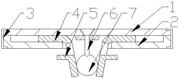
[0017] The present invention is described in further detail now in conjunction with accompanying drawing. These drawings are all simplified schematic diagrams, which only illustrate the basic structure of the present invention in a schematic manner, so they only show the configurations related to the present invention.

[0018] Such as figure 1 As shown, the present invention is a door hinge fixed plate connection structure, including an upper splint and a lower splint fixedly connected to each other, a fixed interlayer is arranged between the upper splint and the lower splint, and two mirror-symmetrical arrangements are arranged in the fixed interlayer. Clamping plate, the clamping plate is arc-shaped, one end of the clamping plate is clamped in the fixed interlayer, an opening is arranged in the middle of the lower clamping plate, and the other end of the clamping plate extends to the outside of the fixed interlayer through the opening ; A number of turning protrusions are arr


PUM


Abstract

The invention relates to a connection structure of a door hinge fixing plate, which comprises an upper splint and a lower splint fixedly connected to each other, a fixed interlayer is arranged between the upper splint and the lower splint, and two clamping plates are mirror-symmetrically arranged in the fixed interlayer , the clamping plate is arc-shaped, one end of the clamping plate is clamped in the fixed interlayer, an opening is arranged in the middle of the lower clamping plate, and the other end of the clamping plate extends to the outside of the fixed interlayer through the opening; There is an expansion screw threaded in the middle of the upper splint, and an expansion column is arranged between the clamping plates. The expansion column is cylindrical, and its side wall is in contact with the inner side wall of the clamping plate. The surface is set in several conical positioning holes, the axis of the positioning holes is located on the radial axis of the expansion column, and the end of the expansion screw is tapered, contacting the positioning holes of the expansion block.

Description


Claims


Application Information

Patent Timeline
Owner JIANGYIN TONGQI HARDWARE ELECTRICAL APPLIANCE FACTORY
Why Eureka
Try Eureka