Mercurial thermometer box provided with sulfur powder
A mercury thermometer and sulfur powder technology, which is applied in the packaging, packaging, packaging types and other directions of fragile items, can solve problems such as physical harm, mercury leakage, poisoning, etc., and achieve the effect of reducing harm
- Summary
- Abstract
- Description
- Claims
- Application Information
AI Technical Summary
Problems solved by technology
Method used
Image

Examples
Embodiment 1
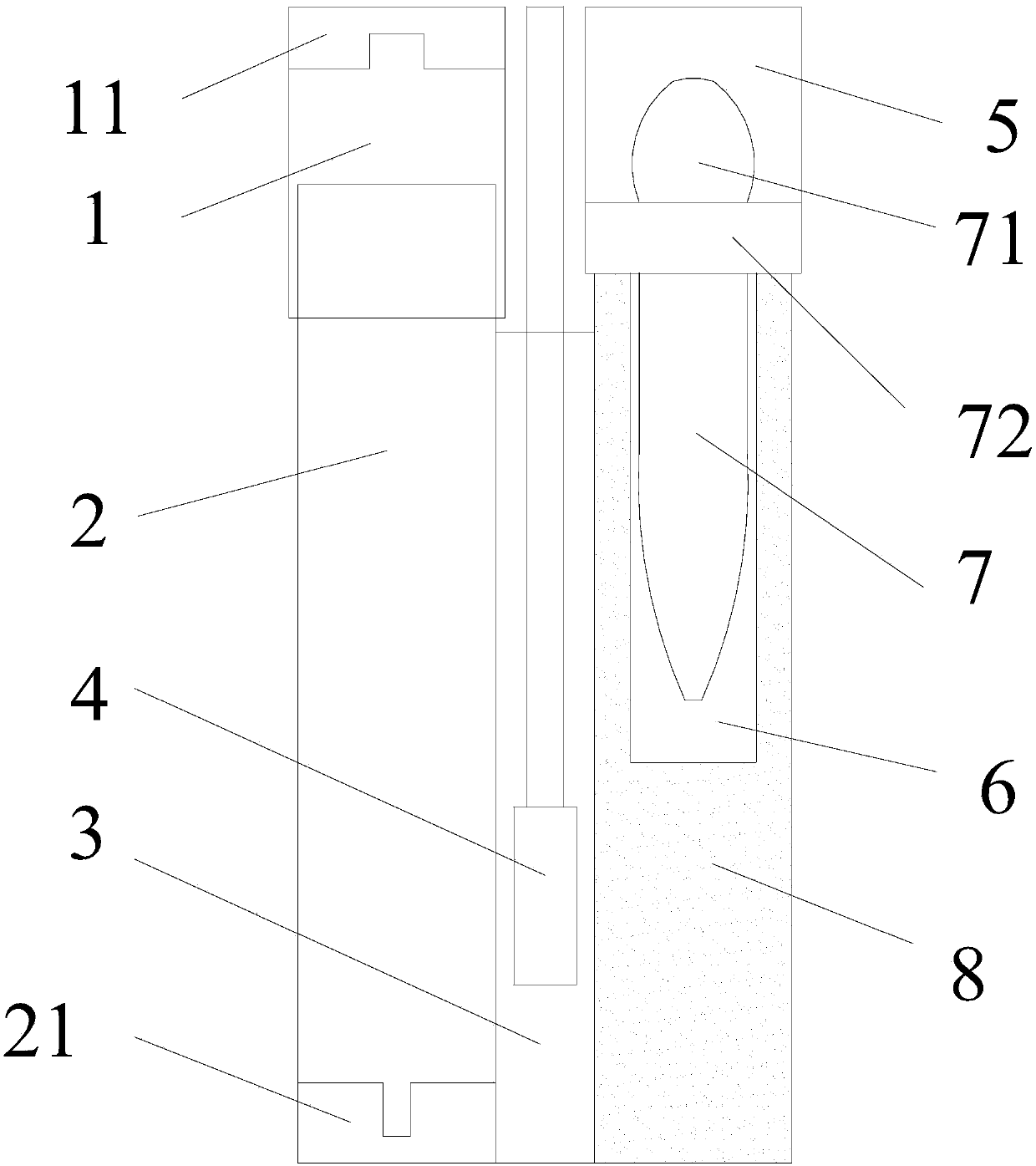
[0020] The mercury thermometer box of the present invention comprises a top cover 1, a box body 2, an upper fixing groove 11, a lower fixing groove 21, a middle cavity 3, and a right cavity, the upper fixing groove 11 is fixedly arranged on the inner top of the top cover 1, and the lower fixing groove 21 is fixedly arranged on the inner bottom of the box body 2, the box body 2, the middle chamber 3, and the right chamber are arranged adjacently from left to right, the right chamber is used to place the straw 7, and the middle chamber 3 is used to place water and the cotton swab stick 4.
[0021] Further, the upper port of the middle cavity 3 is provided with a middle cover, and the middle cover is integrated with the cotton swab stick 4, and the wooden stick of the cotton swab stick 4 runs through the middle cover.
[0022] Further, the upper port of the right chamber is provided with a right chamber cover 72 .
[0023] The upper fixing groove 11 and the lower fixing groove 21 ar
Embodiment 2
[0025] The difference between embodiment 2 and embodiment 1 is:
[0026] 1. Divide the right chamber into 8 parts, the suction pipe chamber 6 and the sulfur powder chamber. The two chambers have a right chamber cover 72 in total. There is also a soft rubber plug in the suction pipe chamber 6, which collects the mercury beads After the suction pipe chamber 6 is inside, plug a soft rubber plug to cover the mouth of the suction pipe chamber 6, and then pour sulfur powder on the ground to make it react with the remaining mercury to generate mercury sulfide, and reduce the remaining mercury Volatile hazards to the human body.
[0027] Two, the mercury beads sucked by the suction pipe 7 squeeze into the suction pipe chamber 6 at last, cover the soft rubber stopper and seal it up, and give it to the relevant departments for proper disposal.
[0028] Preferably, the right chamber includes a suction pipe chamber 6 and a sulfur powder chamber 8, the vertical section of the right chamber i
Embodiment 3
[0030] Such as figure 1 As shown, the difference between embodiment 3 and embodiment 2 is that the suction pipe 7 is integrated with the right chamber cover 72, the suction pipe 7 includes a pointed glass tube, a glue head 71, and a right chamber cover 72, and the right chamber cover 72 is fixedly arranged on the glue head 71 and the junction of the pointed glass tube.
[0031] Preferably, an upper cover 5 is provided outside the rubber head 71 to protect the rubber head 71 , so as to prevent the rubber head 71 from being squeezed during normal use, causing the suction pipe 7 to inhale and breathe in the suction pipe cavity 6 .
PUM
 Abstract
Description
Claims
Application Information
 - R&D Engineer
- R&D Manager
- IP Professional
- Industry Leading Data Capabilities
- Powerful AI technology
- Patent DNA Extraction
Browse by: Latest US Patents, China's latest patents, Technical Efficacy Thesaurus, Application Domain, Technology Topic.
© 2024 PatSnap. All rights reserved.Legal|Privacy policy|Modern Slavery Act Transparency Statement|Sitemap