Quick die replacing device

A fast, die-seat technology, used in forging/pressing/hammer devices, manufacturing tools, forging/pressing/hammering machinery, etc., can solve the problems of heavy weight, difficult on-site operation, long downtime for die change, etc. The effect of replacement and reduction of transportation intensity

Pending Publication Date: 2018-01-26
KETENG IND PANYU CITY
View PDF0 Cites 0 Cited by
  • Summary
  • Abstract
  • Description
  • Claims
  • Application Information

AI Technical Summary

Problems solved by technology

Moreover, the movement of the mold changing trolley is not smooth, and the on-site operation is relatively difficult. It takes up to 2 hours to change the mold at a time
Therefore, the efficiency of mold replacement using the traditional fixed-table die forging press is low, which affects the production rhythm. At the same time, the existing mold changing device is bulky and heavy, which brings great inconvenience to the operator during replacement.
[0003] With the development of presses in the direction of multi-variety, high-speed, automation, and flexibility, how to quickly replace molds has become a bottleneck restricting efficient production. Especially for large-tonnage presses, it is more difficult to replace and transport large-scale mold bases. The labor intensity of mold operators is high, and the downtime for mold change is long, which seriously affects the production efficiency of the press

Method used


Image

  • Quick die replacing device
  • Quick die replacing device
  • Quick die replacing device

Examples


Example Embodiment

[0029] The invention provides a quick mold changing device to quickly change molds.

[0030] The technical solutions in the embodiments of the present invention will be clearly and completely described below in conjunction with the accompanying drawings in the embodiments of the present invention. Obviously, the described embodiments are only a part of the embodiments of the present invention, rather than all the embodiments. Based on the embodiments of the present invention, all other embodiments obtained by those of ordinary skill in the art without creative work shall fall within the protection scope of the present invention.

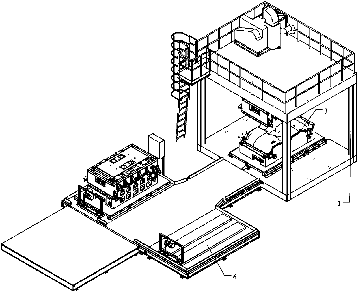
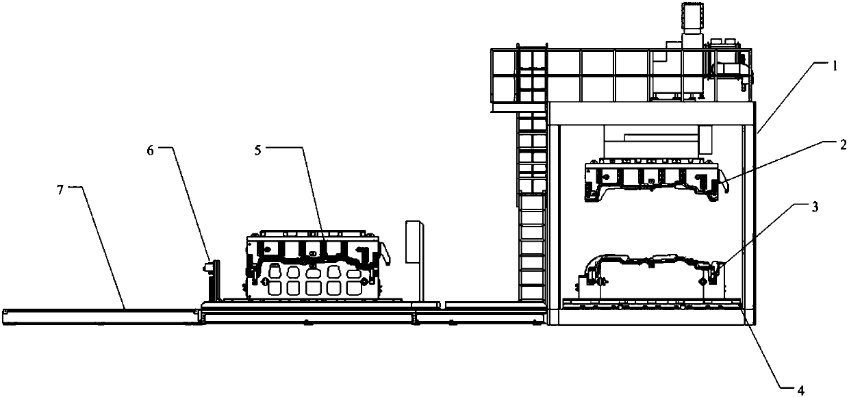
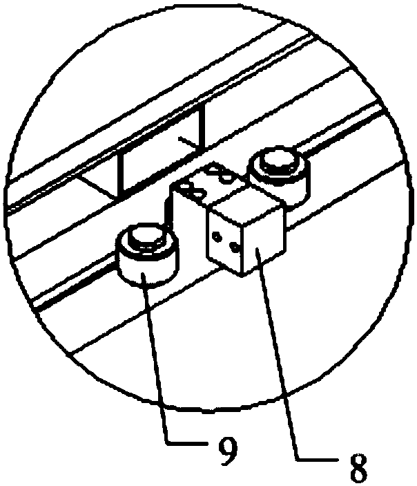
[0031] Such as Figure 1 to Figure 3 As shown, the technical solution of a quick mold change device of the present invention includes:

[0032] Press 1 and air-cushion vehicle 6;

[0033] The press 1 includes an upper mold 2 and a lower mold 3 arranged up and down. The upper mold 2 is detachably mounted on the upper mold base, and the lower mold 3 is detachabl


PUM


Abstract

The invention provides a quick die replacing device and aims to quickly replace a die. According to the technical scheme, the quick die replacing device comprises a press and an air cushion vehicle, wherein the press comprises an upper die and a lower die which are arranged in an upper-lower manner; the upper die is detachably mounted on an upper die seat; the lower die is detachably mounted on alower die seat; the lower die seat can move relative to a base of the press; a die seat guiding groove is arranged below the lower die seat; and the air cushion vehicle extends into or is separated from the die seat guiding groove selectably.

Description


Claims


Application Information

Patent Timeline
Owner KETENG IND PANYU CITY
Why Eureka
Try Eureka