Partial quick-change combination punch for punching when internal high-pressure forming

An internal high pressure, punch technology, applied in the field of machinery, can solve the problem of wasting materials and labor, and achieve the effect of reducing consumption, rapid replacement, and reducing the workload of personnel

Pending Publication Date: 2019-03-29
吉林省正轩车架有限公司
View PDF0 Cites 0 Cited by
  • Summary
  • Abstract
  • Description
  • Claims
  • Application Information

AI Technical Summary

Problems solved by technology

Overcome the waste of material and labor shor

Method used


Image

  • Partial quick-change combination punch for punching when internal high-pressure forming
  • Partial quick-change combination punch for punching when internal high-pressure forming
  • Partial quick-change combination punch for punching when internal high-pressure forming

Examples


Example Embodiment

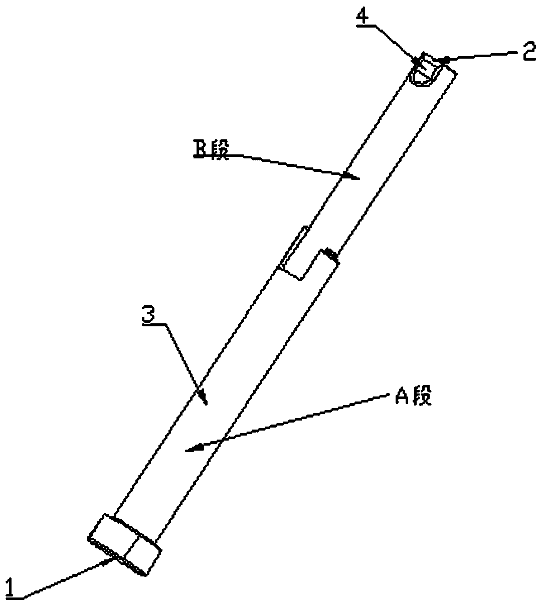
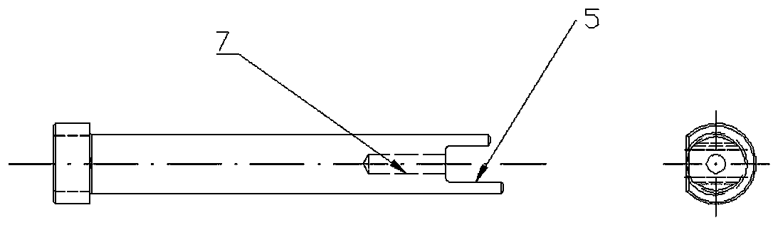
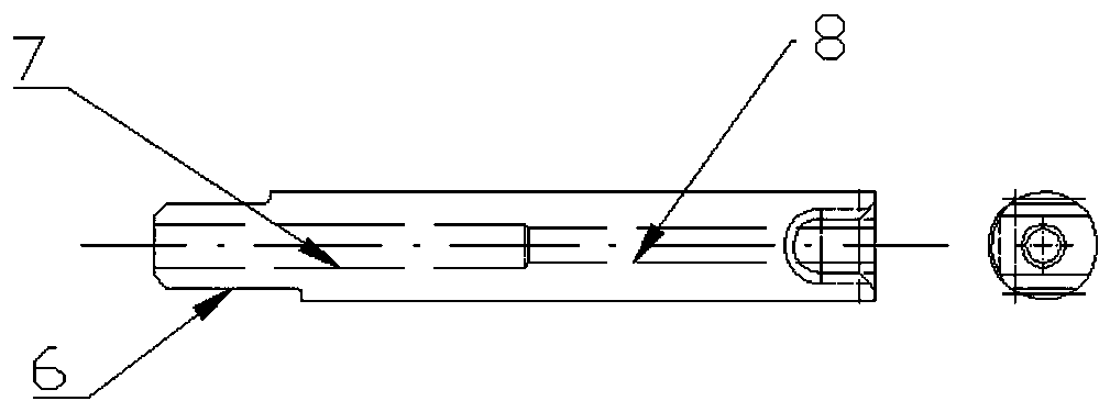
[0014] Refer to figure 1 , The punch of the present invention includes a base 1, which is matched with the punch fixing fixture, a cutting edge 2, punched on the inner high-pressure forming part 2, a cylindrical straight rod part 3 between the base and the cutting edge, wherein the base 1 is A column with a chord-cut circle in cross section. The diameter of the arc part of the cross section of the base 1 is larger than the diameter of the straight rod part 3. The length of the straight rod part is determined by the wall thickness of the mold at the punching point of the molded part. The mouth line is in the shape of a chord tangent circle. The side cut surface 4 on the straight rod at the edge of the punch and the end face of the straight rod intersect to form a chord tangent round edge 2. The axial length of the side cut surface 4 on the straight rod is given by the punch. When it reaches the dead point, the end is still outside the molded part; the improvement is: the punch is di


PUM


Abstract

The invention discloses a partial quick-change combination punch for punching when internal high-pressure forming. The partial quick-change combination punch includes a base matched with a fixture, acutting edge for punching and a straight rod part between the base and the cutting edge. The punch is composed of two segments, an inserting tenon is formed at the connecting end of one punch body, and a tenon opening is formed in the other punch body. Threaded holes with reverse threads and located at the axis are formed in the opposite ends of the two punch bodies. The two punch bodies are connected by a screw with reverse threads at the two ends. An internal hexagonal wrench inserting groove is formed in the end, facing the cutting edge, of the connecting screw, and an axial hole in which ahexagon wrench is inserted is formed in the punch body with the cutting edge. The partial quick-change combination punch has the positive effects that through the design of the segments and a connecting structure after segmenting of the punch as a whole, simple and rapid replacement of faster wearing parts of the punch is realized, the workload of personnel for the punch replacement is reduced, the time for machine halt due to the punch replacement is shortened, the production efficiency is improved, only a part of the entire punch is scrapped, the end with the base can be used for a long time, the consumption of materials is reduced, and reduction of the production cost is facilitated.

Description


Claims


Application Information

Patent Timeline
Owner 吉林省正轩车架有限公司
Why Eureka
Try Eureka