Front longitudinal beam structure

A front longitudinal beam and reinforcing structure technology, which is applied in the substructure, transportation and packaging, vehicle parts, etc., can solve the problems of high input cost in the manufacture of molds and fixtures, unfavorable lightweight development, and many stamping and forming processes. Conducive to lightweight design, saving manufacturing cost and low mold cost

Pending Publication Date: 2018-01-26
SUZHOU ZIJING QINGYUAN NEW ENERGY AUTOMOBILE TECH
View PDF8 Cites 2 Cited by
  • Summary
  • Abstract
  • Description
  • Claims
  • Application Information

AI Technical Summary

Benefits of technology

This technology helps improve the performance of an automobile's headlining system by adding stronger connections between different parts or structures within it without requiring extra materials like metal plating for added durability. Additionally, this new method allows for easier assembly with fewer steps compared to traditional methods while maintaining its effectiveness over time due to improved resistance against corrosives caused from environmental factors such as rainwater. Overall, these technical improvements help make vehicles lighter but still more reliable at their lifespan.

Problems solved by technology

This patented technical problem addressed by this patents relates to improving the design of vehicle's front cross member that can absorb shock during collisions without adding extra weight or complexity compared to existing designs due to its complex construction process involving multiple layers of different types of steels.

Method used


Image

  • Front longitudinal beam structure
  • Front longitudinal beam structure

Examples


Embodiment Construction

[0028] The technical solutions of the present invention will be further described below in conjunction with the accompanying drawings and through specific implementation methods.

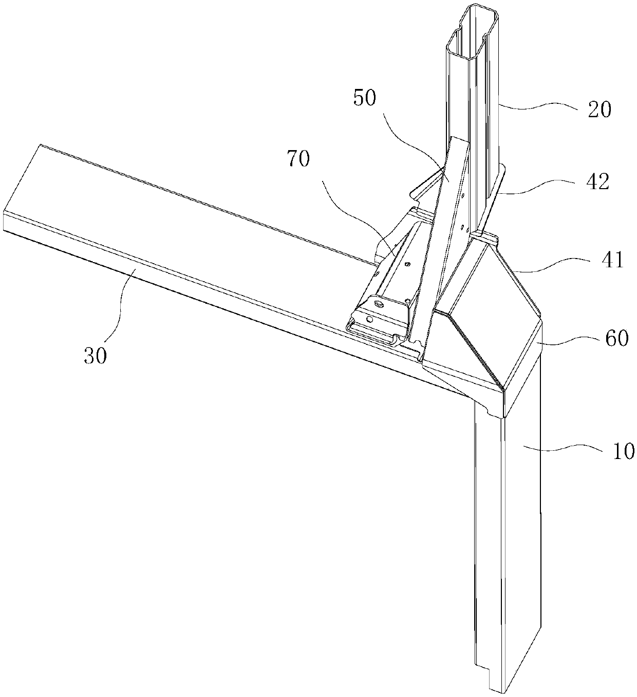
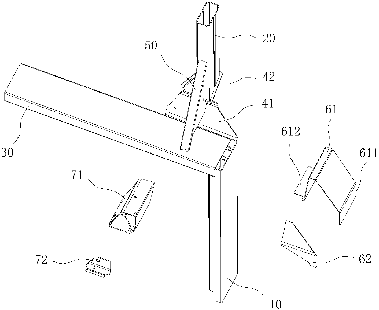
[0029] Such as Figures 1 to 2 As shown, a front longitudinal beam structure includes: a first connecting beam 10 and a second connecting beam 20 arranged longitudinally, and a cross beam 30, and the opposite ends of the first connecting beam 10 and the second connecting beam 20 are connected by a connecting plate 41 One end of the crossbeam 30 is welded to the end of the first connecting beam 10; the connection of the first connecting beam 10, the second connecting beam 20 and the crossbeam 30 is connected with a reinforcement structure, and the structural strength of the connection is improved by the reinforcement structure .

[0030] Specifically, the reinforcement structure includes reinforcing ribs 50 vertically welded to the second connecting beam 20 and the connecting plate 41 , and vertically


PUM


Abstract

The invention discloses a front longitudinal beam structure. The structure comprises a first connecting beam, a second connecting beam and a cross beam, wherein the first connecting beam and the second connecting beam are longitudinally arranged, the opposite ends of the first and second connecting beams are connected with each other through a connecting plate, and one end of the cross beam is welded to the end portion of the first connecting beam; the junctions of the first connecting beam, the second connecting beam and the cross beam are connected with a reinforcing structure, and the reinforcing structure comprises a reinforcing bar welded to the second connecting beam and the connecting plate separately and vertically connected with the cross beam, a first reinforcing member connectedto one side of the reinforcing bar and connected with the first connecting beam and the cross beam separately and a second reinforcing member connected to the other side of the reinforcing bar and the cross beam. The front longitudinal beam structure is high in structural strength and low in weight and manufacturing cost.

Description


Claims


Application Information

Patent Timeline
Owner SUZHOU ZIJING QINGYUAN NEW ENERGY AUTOMOBILE TECH
Why Eureka
Try Eureka