Centrifugation test clamp with fiber type Y waveguide device

A waveguide device, centrifugal test technology, applied in optical instrument testing, machine/structural component testing, instruments, etc., can solve problems such as fiber breakage and low work efficiency, reduce workload, improve efficiency, and improve test work. The effect of efficiency

Active Publication Date: 2018-01-26
THE 44TH INST OF CHINA ELECTRONICS TECH GROUP CORP
View PDF8 Cites 2 Cited by
  • Summary
  • Abstract
  • Description
  • Claims
  • Application Information

AI Technical Summary

Problems solved by technology

[0003] In view of this, the purpose of the present invention is to provide a kind of centrifugal test fixture of Y-waveguide device with optical fiber, this centrifugal test fixture of Y-waveguide device with optical fiber can solve the problem that optical fiber is easy to appear bec

Method used


Image

  • Centrifugation test clamp with fiber type Y waveguide device
  • Centrifugation test clamp with fiber type Y waveguide device
  • Centrifugation test clamp with fiber type Y waveguide device

Examples


Embodiment 1

[0022] Embodiment 1 The design method of the fixture with optical fiber type Y waveguide device

[0023] First, determine the design specifications of the fixture according to the vulnerable parts of the Y waveguide device

[0024] Determine the contact surface material of the vulnerable part through the vulnerable part of the Y waveguide, determine the size and structure of the fixture according to the size of the product test volume and the clamping requirements of the test equipment, and determine the fixture's weight according to the requirements of the mechanical test on the balance of the fixture and the weight of the fixture. Materials, and structural design based on the above factors.

[0025] Through the statistics of the failure parts of the product during the centrifugal test, the main force-bearing surface of the device during the test, and the state of the product in actual application, determine the fiber root of the Y-waveguide with fiber-optic device, the bottom c

Embodiment 2

[0032] Example 2 Centrifugal test fixture with optical fiber Y waveguide device

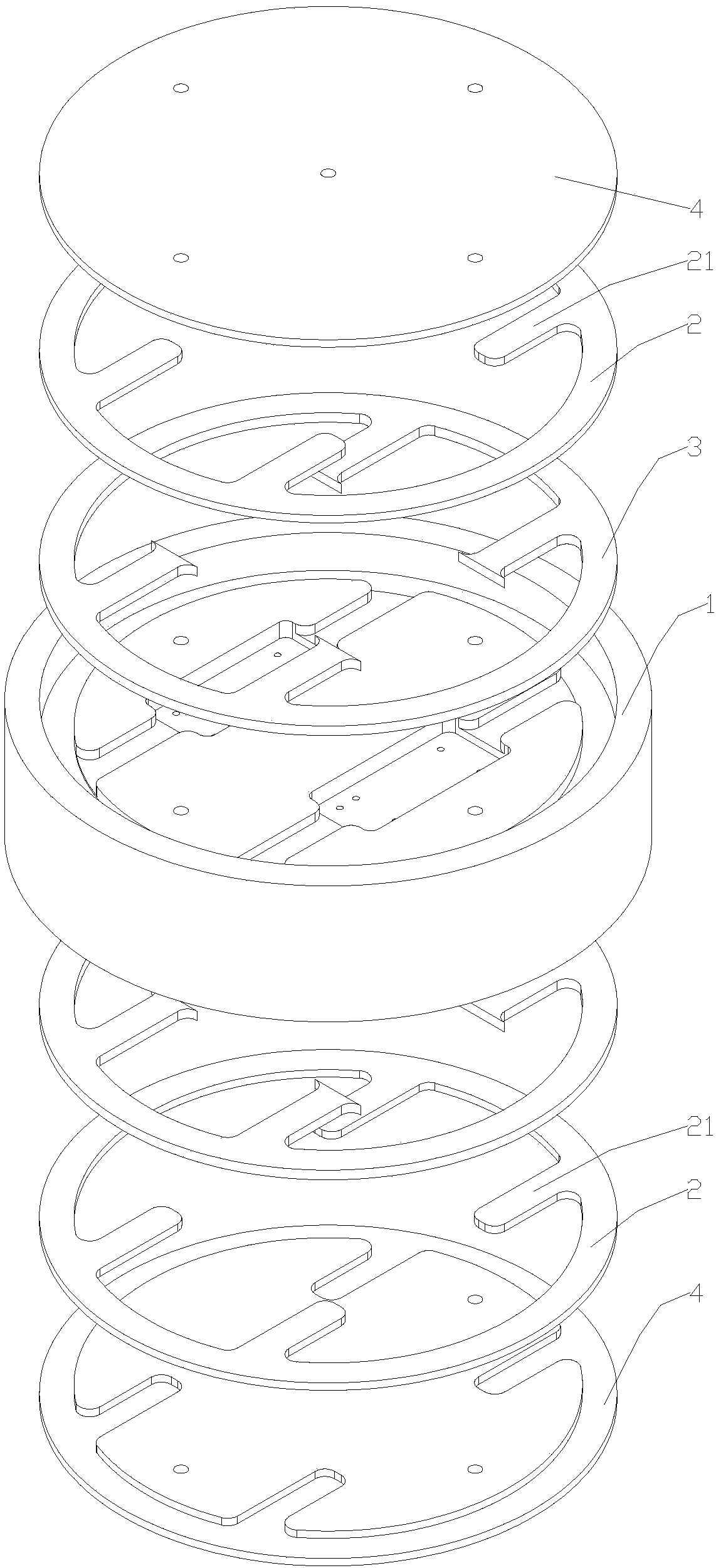
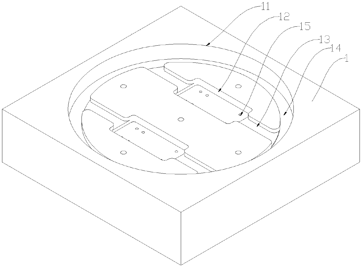
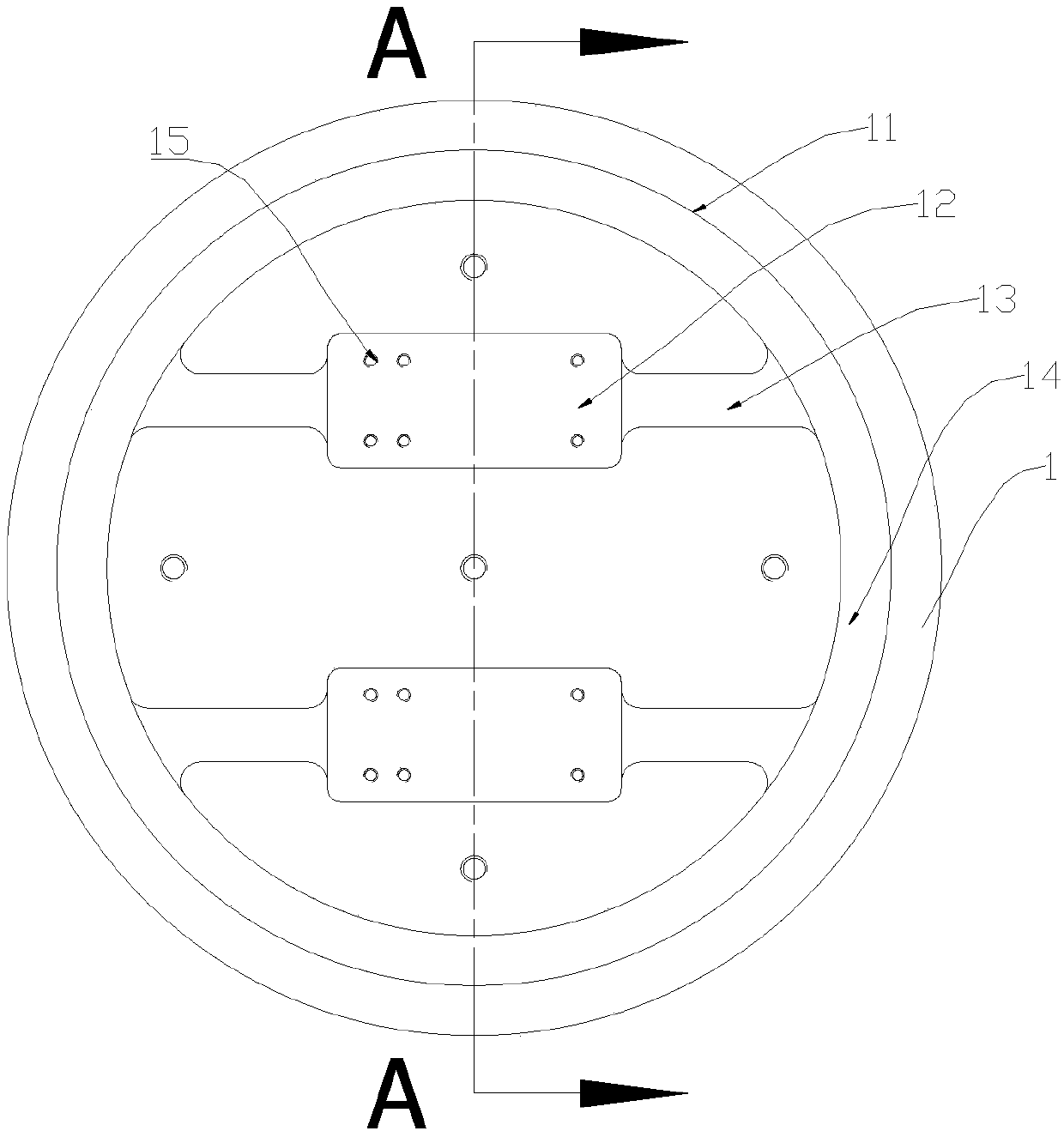
[0033] Such as Figures 1 to 6 As shown: the centrifugal test fixture with fiber-optic Y waveguide device in this embodiment includes a cover plate 4, an outer gasket 2, an inner gasket 3 and a device mounting seat 1 installed sequentially from outside to inside, and the end surface of the device mounting seat 1 There is a columnar groove 11 on it, and at least one retention groove A12 whose size and shape are compatible with the Y waveguide device to be tested is provided on the bottom plane of the groove 11, and the bottom of the retention groove A12 is provided with A plurality of holes 15; a fixing groove B13 for fixing the optical fiber is opened between the middle part of the fixing groove A12 and the bottom edge of the groove 11, the fixing groove A12 and the fixing groove B13 communicate with each other, and the inner gasket 3 is provided with There is a gasket A31 extending toward the reta


PUM


Abstract

The invention discloses a centrifugation test clamp with a fiber type Y waveguide device. The centrifugation test clamp comprises a cover plate, an outer gasket, an inner gasket and a device mountingseat which are sequentially mounted from outside to inside, wherein an end surface of the device mounting seat is provided with a column-shaped groove, a plane of a bottom portion of the groove is atleast provided with a fixed groove A which is matched with the to-be-tested Y waveguide device in size and shape, a fixed groove B used for fixing fiber is arranged between the middle portion of the fixed groove A and an edge of the bottom portion of the groove, the fixed groove A and the fixed groove B are mutually communicated, and the inner gasket is provided with a pad A which extends towardsthe fixed groove A and is mutually matched with the fixed groove B. The centrifugation test clamp is advantaged in that a problem of low work efficiency caused by replacement of the clamp during a centrifugation test, a vibration test and an impact test existing in a Y waveguide device in the prior art is solved, efficiency of the Y waveguide device during a mechanical test is substantially improved, and the completion time of three tests accomplished by the Y waveguide device is shorted by one third.

Description


Claims


Application Information

Patent Timeline
Owner THE 44TH INST OF CHINA ELECTRONICS TECH GROUP CORP
Why Eureka
Try Eureka