Triaxial synthesis oscillation/impact test device

A shock test and platform technology, which is applied in the field of oblique three-dimensional vibration/shock test equipment, can solve the problems of low work efficiency, many labors, and long time consumption, and achieve the effect of simple structure and high test operation efficiency

Inactive Publication Date: 2009-06-10
704TH RES INST OF CHINA SHIPBUILDING IND CORP
View PDF0 Cites 8 Cited by
  • Summary
  • Abstract
  • Description
  • Claims
  • Application Information

AI Technical Summary

Benefits of technology

This patented technology uses an oscillating platform that works like a triangular prism with two parallel plates attached together by springs or rubber bands. By applying pressure on one plate while also allowing it to move freely around within this other plate, any changes made during testing will cause slight movements along its own axis without affecting their ability to perform useful work effectively. Additionally, this design allows for easy replacement when needed due to changing conditions such as temperature fluctuations or humidity levels. Overall, these technical features make it ideal for various applications involving vibrational tests (such as manufacturing validation).

Problems solved by technology

This patents discusses testing materials during flight operations against severe weather challenges due to factors like temperature changes (temperature) and humidity levels. Current methods involve either expensive special instruments or complicated procedures requiring trained staffs. Additionally, current solutions lack flexibility because they require separate excitations to apply force to the material being tested.

Method used


Image

  • Triaxial synthesis oscillation/impact test device

Examples


Embodiment Construction

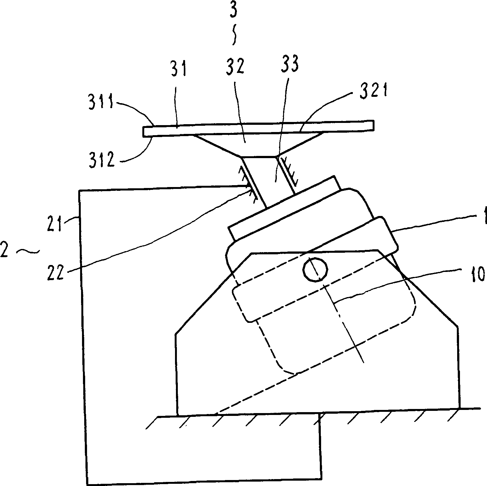
[0010] refer to figure 1 , The three-axis comprehensive vibration / shock test device includes a vibration table body 1, a base 2, and an extension table assembly 3.

[0011] The structure of the vibrating table body 1 is the same or similar to the existing hydraulic or electromagnetic vibrating table. The vibrating table body 1 is installed on the base 2 of the vibrating table surface through a fixing device, and the corresponding extended table surface is in an inclined state, that is, vibrating The axis 10 of the table body 1 (including the excitation source) and the vertical line form an inclination angle θ (such as figure 1 As shown), this structure can decompose the vibration in a single direction along the axis 10 of the shaking table body into the components of any axis on the three-dimensional coordinate axis, that is, one vibration test can meet the requirements of three-dimensional axial test. Compared with the traditional test The vibration excitation in one coordina


PUM


Abstract

The invention relates to a triaxial comprehensive vibration/impulsion test apparatus which mainly solves technical problems for improving working efficiency and test reliability. The technical solution is that the upper end of an inclined vibration stage axle is provide with an expandable stage assembly whose table top is in horizontal status which is suitable for triaxial inclined 3-D vibration test stage.

Description


Claims


Application Information

Patent Timeline
Owner 704TH RES INST OF CHINA SHIPBUILDING IND CORP
Why Eureka
Try Eureka