High voltage isolation switchgear cable chamber door interlocking device

A technology of isolation switch and high-voltage isolation, applied in the direction of air switch parts, etc., can solve the problems of complex structure of mechanical interlocking device, inconvenient installation and maintenance, complex transmission process, etc., to achieve easy promotion and implementation, convenient installation and maintenance, and reliable connection. Effect

Inactive Publication Date: 2018-01-30
CHENGDU HENGTONG ZHAOYE PRECISION MACHINERY
View PDF6 Cites 0 Cited by
  • Summary
  • Abstract
  • Description
  • Claims
  • Application Information

AI Technical Summary

Benefits of technology

This new design allows for better control over an isolated switching device's operation without requiring physical contact or remote monitoring from other devices like sensors that are used to detect if there is any problem happening around it. It also simplifies its construction while maintaining reliability during use.

Problems solved by technology

The technical problem addressed in this patents relates to improving the design of isolated switches used at various levels of voltages such as 3 - 1000 VACs without causing damage caused by excessively large currents generated through them. Current methods involve using expensive materials like metal plugs and conductor wires, but these techniques result in poor performance and potential hazards if they occur unexpectedly.

Method used


Image

  • High voltage isolation switchgear cable chamber door interlocking device
  • High voltage isolation switchgear cable chamber door interlocking device
  • High voltage isolation switchgear cable chamber door interlocking device

Examples


Embodiment

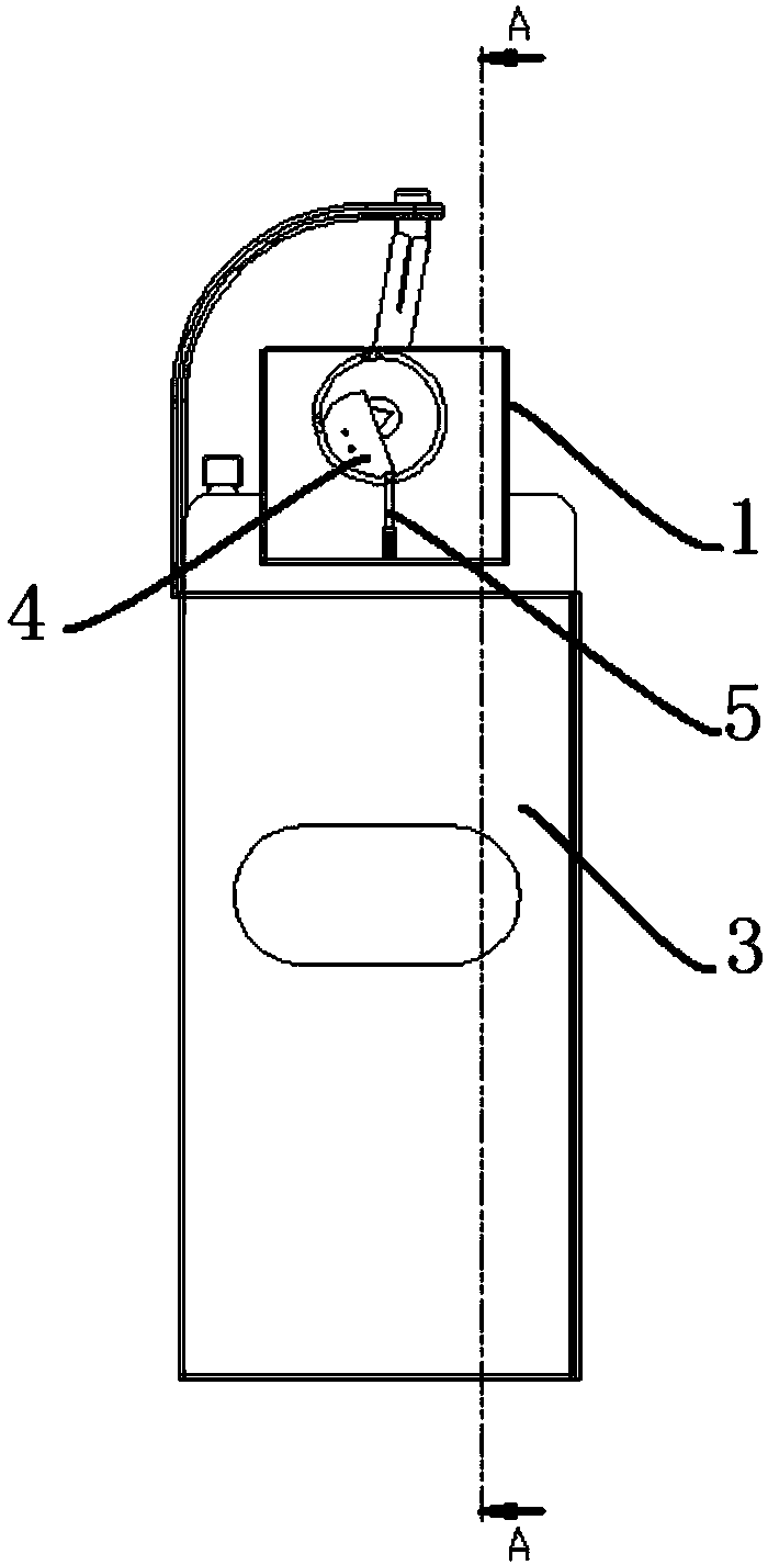
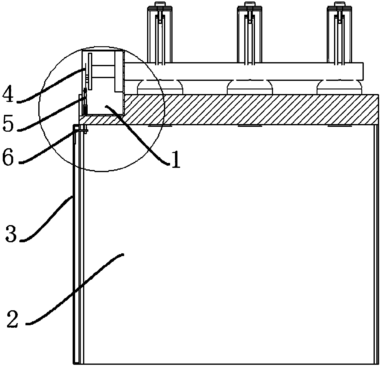
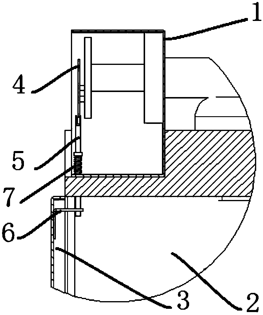
[0024] Such as Figure 1 to Figure 6 As shown, an interlocking device for a cable compartment door of a high-voltage isolating switch cabinet according to the present invention includes an isolating switch operating mechanism 1 , an isolating switch housing 2 , and a cable compartment door 3 . The lower end of the isolating switch operating mechanism 1 is connected to the isolating switch housing 2 by bolts, and the front left vertical beam of the isolating switch housing 2 is connected to the left vertical beam of the cable compartment door 3 through a hinge, and the cable compartment door 3 rotates around the hinge to open or close cable room. The isolating switch operating mechanism 1 is provided with a curved plate 4, which is fixedly installed on the operating shaft of the isolating switch operating mechanism 1, the outer edge of the curved plate 4 is provided with a driving curved surface, and the lower end of the curved plate 4 is movably connected with an interlocking rod


PUM


Abstract

The invention discloses a high voltage isolation switchgear cable chamber door interlocking device which comprises an isolation switch operating mechanism, an isolation switch casing body and a cablechamber door. The device is characterized in that the lower end of the isolation switch operating mechanism is connected with the isolation switch casing body; a curved plate is arranged on the isolation switch operating mechanism; a drive curved surface is arranged on the outer edge of the curved plate; the lower end of the curved plate is movably connected with an interlocking rod; the interlocking rod is movably arranged in a round hole in the bottom surface of the isolation switch operating mechanism; a locking plate is fixedly arranged on the inner side of the cable chamber door; and a locking hole which matches the interlocking rod is arranged on the locking plate. According to the invention, the curved plate is arranged on the isolation switch operating mechanism; when the isolationswitch is closed, the second curved surface of the curved plate presses down the interlocking rod; the interlocking rod locks the locking plate of the cable chamber door, and the cable chamber door cannot be opened; and the interlocking mechanism has the advantages of simple structure, safety, reliability, convenient installation and maintenance, convenient inspection, low manufacture cost, beingmaintenance-free and convenient popularization and implementation.

Description


Claims


Application Information

Patent Timeline
Owner CHENGDU HENGTONG ZHAOYE PRECISION MACHINERY
Why Eureka
Try Eureka