Eye tracker and image processing method
An eye tracker and image information technology, applied in diagnostic signal processing, medical science, sensors, etc., can solve the problems of inaccurate measurement of eyeball distance, time-consuming and laborious, research troubles and obstacles, etc., and achieve easy operation, simple processing, and fast tracked effect
- Summary
- Abstract
- Description
- Claims
- Application Information
AI Technical Summary
Benefits of technology
Problems solved by technology
Method used
Image


Examples
Embodiment 1
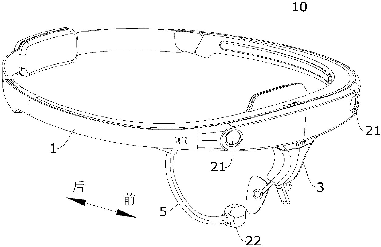
[0048] figure 1 is a perspective view of an eye tracker 10 according to an embodiment of the present invention, figure 2 is a front view of the eye tracker 10 according to an embodiment of the present invention. The eye tracker 10 includes a head-mounted body 1 . The head-mounted main body 1 is roughly in the shape of a ring, and may be of an integral structure or of a split structure. The eye tracker 10 also includes a plurality of front cameras 21 . A plurality of front cameras 21 are arranged on the head-mounted body 1 at intervals along the circumferential direction, and at least two of the plurality of front cameras 21 can simultaneously collect image information of a target scene in front of the head-mounted body 1 . The image information includes videos, images and / or pictures.
[0049] The eye tracker 10 also includes a control system ( figure 1 and figure 2 not shown in ). The installation location of the control system is not particularly limited, and it can be
Embodiment 2
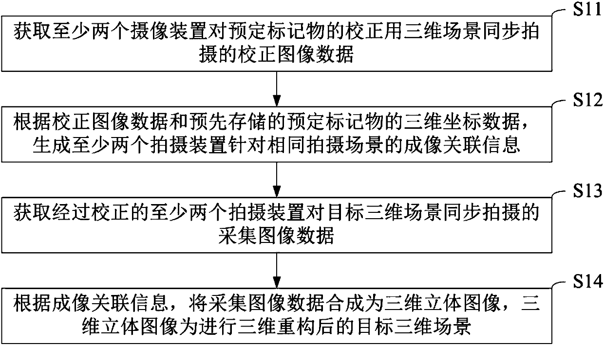
[0064] Such as image 3 As shown, the image processing method for three-dimensional reconstruction in the embodiment of the present invention includes the following steps:
[0065] Step S11: Acquiring the corrected image data synchronously captured by at least two camera devices in the 3D scene for the calibration of the predetermined marker;
[0066] Step S12: According to the corrected image data and the pre-stored three-dimensional coordinate data of predetermined markers, generate imaging related information of at least two shooting devices for the same shooting scene;
[0067] Step S13: Obtain the collected image data of the target 3D scene captured synchronously by at least two corrected shooting devices;
[0068] Step S14: Synthesize the collected image data into a 3D stereo image according to the imaging association information, and the 3D stereo image is the target 3D scene after 3D reconstruction.
[0069] It should be noted that the types and imaging parameters of th
Embodiment 3
[0090] Such as Figure 5 As shown, the embodiment of the present invention is used to analyze the image processing method of target object attention degree, comprises the following steps:
[0091] Step S21: Obtain the image data captured by the front camera, the image data includes the image information of the predetermined marker and the image information of the target object, and the relative positional relationship between the predetermined marker and the target object is fixed;
[0092] Step S22: Obtain the subject's eye data captured by the eye camera;
[0093] Step S23: According to the eye data, determine the focus area of the subject in the corresponding image data;
[0094] Step S24: Determine the location area of the target object in the image data according to the image information of the predetermined marker in the image data;
[0095] Step S25: Determine whether the location area falls into the focus area, if it does, it is determined that the subject has paid
PUM
 Abstract
Description
Claims
Application Information
 - R&D Engineer
- R&D Manager
- IP Professional
- Industry Leading Data Capabilities
- Powerful AI technology
- Patent DNA Extraction
Browse by: Latest US Patents, China's latest patents, Technical Efficacy Thesaurus, Application Domain, Technology Topic.
© 2024 PatSnap. All rights reserved.Legal|Privacy policy|Modern Slavery Act Transparency Statement|Sitemap