Three-claw cutter head

A technology of cutter head and cutter holder, which is applied to milling cutters, attachments of cutter holders, tools for lathes, etc., can solve problems such as troubles, and achieve the effect of convenient clamping and high machining accuracy

Inactive Publication Date: 2018-03-13
肖南萍
View PDF7 Cites 0 Cited by
  • Summary
  • Abstract
  • Description
  • Claims
  • Application Information

AI Technical Summary

Problems solved by technology

[0002] Some existing mechanical parts, especially the precision of the inner wall of the step surface of some parts, often use milling cutters to further improve the precision of the hole wall, or the hole walls of the inner holes of some parts use boring cutters to further improve the precision of the hole wall. Processing a part requires a tool, which is more troublesome

Method used


Image

  • Three-claw cutter head

Examples


Example Embodiment

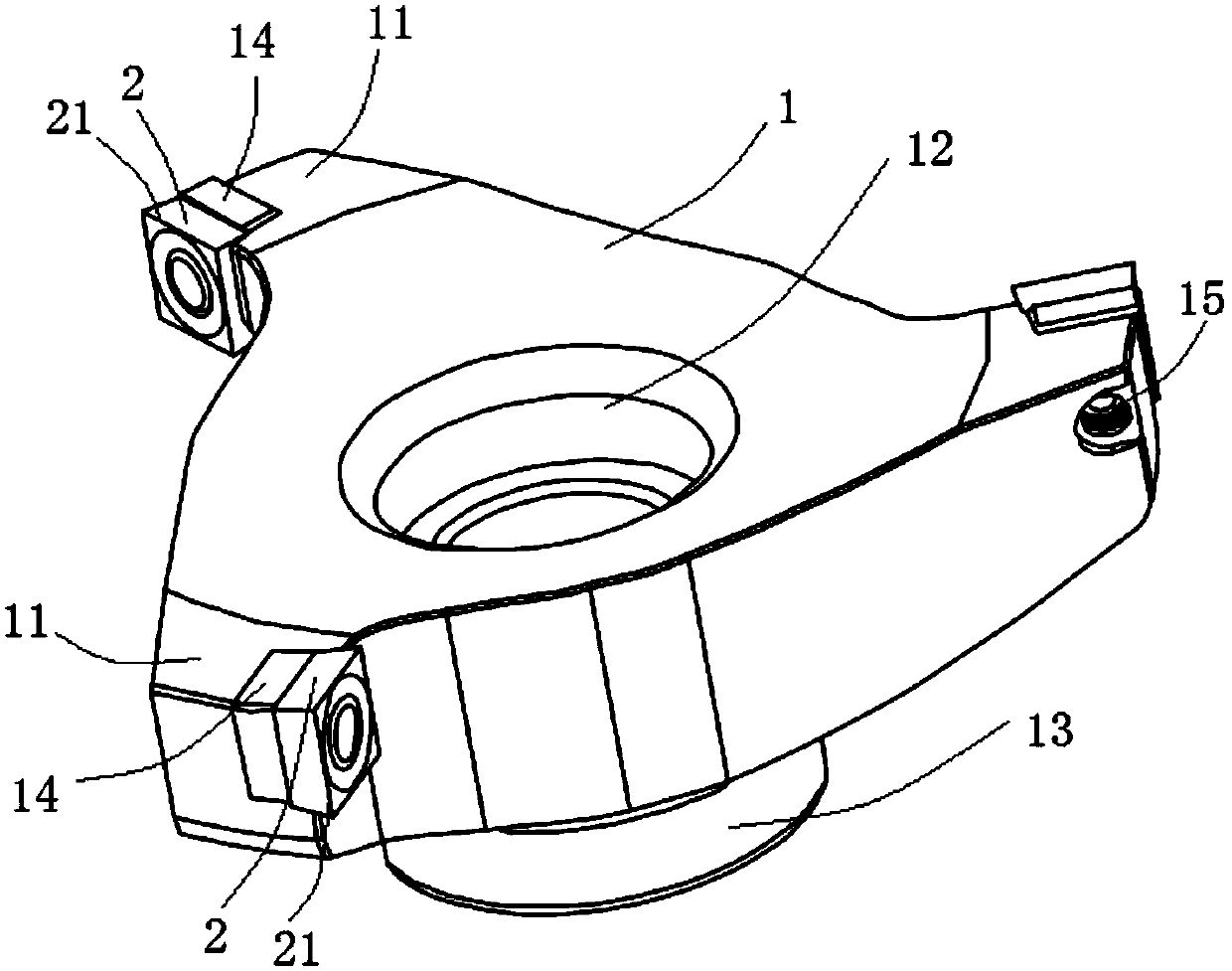
[0013] The following will be attached figure 1 The present invention is described in detail: the present invention includes a knife holder 1 and a blade 2. The knife holder 1 is a revolving structure. The edge of the knife holder 1 is protruded with three equally distributed brackets 11, and the three The bracket 11 is inclined counterclockwise around the tool holder 1; the center of the tool holder 1 is provided with a mounting hole 12, and a clamping body 13 penetrating the mounting hole 12 is installed on one side of the tool holder 1, through which The clamping body 13 and the mounting hole 12 install the tool holder 1 on the processing equipment; the blade 2 is fixed on the mounting frame 14 provided by the three brackets 11, and arranged in a counterclockwise direction, and the blade 2 The knife edge 21 is higher than the upper plane and the outer side of the tool holder 1; the protruding size of the bracket 11 of the three-jaw cutter head can be set according to the diamete


PUM


Abstract

The invention relates to a three-claw cutter head which comprises a cutter frame and blades. The cutter frame is of a rotation body structure. Three supports which are distributed at equal intervals are arranged on the edge of the cutter frame in a protruding and extending manner, and the three supports incline around the cutter frame in the anticlockwise direction. An installation hole is formedin the center of the cutter frame. A clamping body penetrating the installation hole is installed on one side of the cutter frame. The cutter frame is installed on machining equipment through the clamping body and the installation hole. The blades are fixed to installation frames arranged on the three supports and arranged in the anticlockwise direction, wherein the cutting edges of the blades arehigher than the upper plane and the outer side face of the cutter frame. The three-claw cutter has the beneficial effects that due to the design of the cutter frame and the installation manner of theblades, the cutter head can be suitable for machining the step face inner wall precision of parts or the inner hole wall precision of the parts and has the beneficial effects that the machining precision is high, clamping is convenient, and two purposes are integrated.

Description


Claims


Application Information

Patent Timeline
Owner 肖南萍
Why Eureka
Try Eureka