Method for realizing cyber-physical system (CPS) model and model thereof

A technology of information-physics fusion and modeling, applied in the field of informatization, can solve problems such as heterogeneous systems and equipment connectivity issues that are not given

Active Publication Date: 2018-03-16
黄强
View PDF5 Cites 0 Cited by
  • Summary
  • Abstract
  • Description
  • Claims
  • Application Information

AI Technical Summary

Benefits of technology

This patented technology allows for better understanding by comparing different methods or models from previous systems. It uses an interconnected network called Cyber Physical Systems Interface ("CSI") that connects hardware devices together without any disruption during communication. By doing this, it provides more reliable connections over longer periods than previously possible due to its ability to communicate through wireless signals.

Problems solved by technology

This patented describes a way that allows companies or organizations to create networks with multiple types of machines called servers. These computers work together like one machine but they communicate through separate channels - connections made by connecting them into a single unit. However, these connections may still exist even if some parts were removed altogether due to failures during maintenance. To address this issue, the patents propose implementing a specialized interface protocol on top of their server's firmware layer to allow data exchange across both hardware layers without affecting any functionality provided within the computer itself.

Method used


Image

  • Method for realizing cyber-physical system (CPS) model and model thereof
  • Method for realizing cyber-physical system (CPS) model and model thereof
  • Method for realizing cyber-physical system (CPS) model and model thereof

Examples


Embodiment Construction

[0031] The implementation of the present invention is described below through specific examples and in conjunction with the accompanying drawings, and those skilled in the art can easily understand other advantages and effects of the present invention from the content disclosed in this specification. The present invention can also be implemented or applied through other different specific examples, and various modifications and changes can be made to the details in this specification based on different viewpoints and applications without departing from the spirit of the present invention.

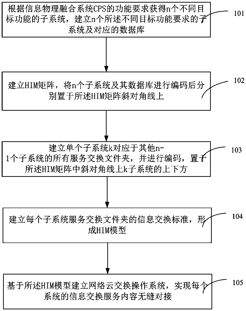
[0032] figure 1 It is a flow chart of steps of a method for realizing a CPS model of a cyber-physical fusion system in the present invention. Such as figure 1 As shown, a method for realizing the CPS model of the cyber-physical fusion system of the present invention comprises the following steps:

[0033] Step 101, obtain n different target functions according to the functional requirements


PUM


Abstract

The invention discloses a method for realizing a cyber-physical system (CPS) model and the model thereof. The method includes the following steps: step 1, obtaining n subsystems with different targetfunctions according to the functional requirements of a CPS, and establishing n subsystems with different target functional requirements and corresponding databases; step 2, establishing an HIM matrix, encoding the n subsystems and the databases, and separately placing the subsystems and the databases on an oblique diagonal of the HIM matrix; step 3, establishing all service exchange folders corresponding to a single subsystem, encoding the folders, and placing the folders above and below the oblique diagonal of the HIM matrix; step 4, establishing information exchange standards for the service exchange folders of each subsystem to form an HIM model; and step 5, establishing a network cloud exchange operating system based on the HIM model to realize a seamless connection between contents and formats of information exchange services of each system. According to the scheme of the invention, the 'Internet of services' for performing the seamless connection among all software and hardwaresubsystems can be achieved.

Description


Claims


Application Information

Patent Timeline
Owner 黄强
Why Eureka
Try Eureka