Calibration technology-based encoder precision improving method
An encoder, high-precision technology, applied in the direction of instruments, measuring devices, etc., can solve problems such as unsatisfactory results, increased hardware costs, and difficulty in improving encoder accuracy, and achieves wide application range, improved accuracy and resolution, and portability strong effect
- Summary
- Abstract
- Description
- Claims
- Application Information
AI Technical Summary
Benefits of technology
Problems solved by technology
Method used
Image

Examples
Embodiment 1
[0053] Embodiment 1, a method for improving the accuracy of an encoder based on a calibration technology, the method aims at an encoder with high resolution and low accuracy without increasing hardware or reducing the resolution of the encoder, and improving the encoder by using a polynomial calibration algorithm The accuracy; the polynomial calibration algorithm and calibration parameters are stored in the programmable digital processor inside the encoder. When the encoder is working, the polynomial calibration algorithm calls the calibration parameters to calibrate the encoder angle to improve the accuracy of the encoder.
[0054] The programmable digital processor is selected from single-chip microcomputer, DSP, FPGA or PLD.
[0055] The polynomial calibration algorithm uses a first-order polynomial fitting algorithm for data calibration, and the calibration parameters are segmented first-order polynomial fitting parameters. When the encoder is working, the programmable process
Embodiment 2
[0092] Embodiment 2, a method for improving encoder accuracy based on calibration technology:
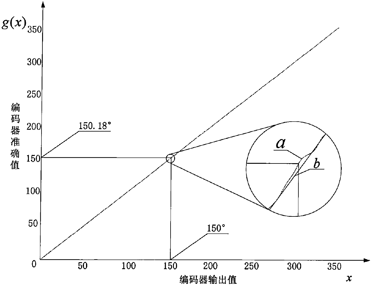
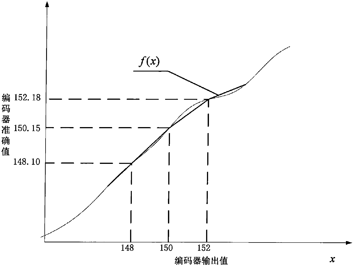
[0093] For each encoder, the mapping from its output value to the exact value is called the encoder’s exact value mapping function such as figure 1 , hereinafter referred to as the mapping function f(x), this function contains information such as the shafting error and conversion error of the encoder. Perform n-order polynomial fitting on the mapping function, the expression is as follows:
[0094]
[0095] where a j is an undetermined coefficient, which can be calculated by the following formula:
[0096]
[0097] where x i (i=1, 2...n) is the continuous n encoder output data of the fitting segment, f(x) i (i=1, 2...n) are exact values corresponding thereto. Obtain x by means of measurement i with f(x) i Then the undetermined coefficient a can be calculated j Thus, an n-order polynomial fitting function f(x) of the mapping function is obtained.
[0098] In order to si
Embodiment 3
[0105] Embodiment 3, a method for improving encoder accuracy based on calibration technology:
[0106] The mapping function f(x) of the encoder from the output original angle to the actual angle is obtained by means of measurement. Connect the turntable with the encoder coaxially, and read the turntable data Z 1 , and record the encoder output B at the same position 1 , after the turntable rotates at a certain angle and stops, record the turntable data Z 2 and encoder data B 2 . Get the turntable angle array Z and the corresponding encoder array B. The array Z and the array B are fitted using the cftool tool in matlab to obtain the mapping function f(x).
[0107] Assuming that the motion mode of the encoder is constant speed motion, the predicted angle of the encoder can be obtained according to the historical angle. The formula is as follows:
[0108] alpha p = 2·α a (n)+α a (n-1) (12)
[0109] According to the above, the encoder mapping angle α can be calculated and
PUM
| Property | Measurement | Unit |
|---|---|---|
| Diameter | aaaaa | aaaaa |
Abstract
Description
Claims
Application Information
 - R&D Engineer
- R&D Manager
- IP Professional
- Industry Leading Data Capabilities
- Powerful AI technology
- Patent DNA Extraction
Browse by: Latest US Patents, China's latest patents, Technical Efficacy Thesaurus, Application Domain, Technology Topic.
© 2024 PatSnap. All rights reserved.Legal|Privacy policy|Modern Slavery Act Transparency Statement|Sitemap