Throttling device

An equipment and current limiting technology, applied in mechanical equipment, lift valves, safety valves, etc., can solve problems such as water waste and water waste, and achieve the effect of small water obstruction and large flow space

Pending Publication Date: 2018-04-20
甘肃腾越电子科技有限公司
View PDF0 Cites 3 Cited by
  • Summary
  • Abstract
  • Description
  • Claims
  • Application Information

AI Technical Summary

Problems solved by technology

Therefore, it is particularly important to use water-saving pipes and equipment. In daily life, water is often wasted due to excessive water flow and

Method used


Image

  • Throttling device

Examples


Embodiment Construction

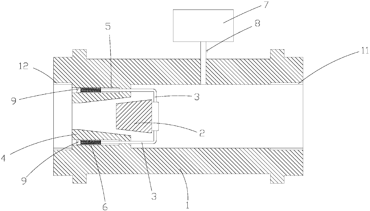
[0011] The present invention is described in detail below in conjunction with accompanying drawing and specific embodiment:

[0012] Such as figure 1 The throttling device shown includes a water pipe main body 1, a flow limiting block 2, a connecting rod 3, a flow limiting surface 4, a spring 6, and an adjusting bolt 9. The two ends of the water pipe main body 1 are respectively provided with inlet connection ends 11 and The outlet connection end 12, the outlet connection end 12 of the water pipe main body 1 is integrally formed with a flow-limiting surface 4, and a flow-limiting cavity 41 is formed inside the flow-limiting surface 4, and the cross-sectional area of ​​the flow-limiting cavity 41 is larger than that of the inlet connection end. 11 is linearly decreasing towards the outlet connection end 12, the restrictor block 2 is set as a frustum structure matching the shape of the restrictor chamber 41, and the restrictor block 2 is placed in the restrictor chamber 41, the res


PUM


Abstract

The invention discloses a throttling device, which comprises a water pipe main body, a flow limiting block, a connecting rod, a flow limiting surface, a spring and an adjusting bolt. The two ends of the water pipe main body are respectively provided with an inlet connection end and an outlet connection end. The water pipe The outlet connection end of the main body is integrally formed with a flow-limiting surface, and a flow-limiting cavity is formed inside the flow-limiting surface. The cross-sectional area of ​​the flow-limiting cavity decreases linearly from the inlet connection end to the outlet connection end. The upper and lower ends are symmetrically provided with mounting holes, one end of the connecting rod is placed in the mounting hole, the other end of the connecting rod is fixedly installed on the current limiting block, the spring is placed in the mounting hole, and the adjusting bolt passes through the The threaded structure is installed on the outer end of the mounting hole, one end of the spring is fixedly connected with the connecting rod, and the other end of the spring is against the adjusting bolt. This equipment can be adjusted according to the water pressure of the flow, so that the water flow in the pipeline is always at a stable value, and the purpose of saving water is achieved.

Description


Claims


Application Information

Patent Timeline
Owner 甘肃腾越电子科技有限公司
Why Eureka
Try Eureka