Fault diagnosis method and device for transformer station grounding network

A substation grounding grid, fault diagnosis technology, applied in the direction of fault location, measuring device, measuring electricity, etc.

Inactive Publication Date: 2018-05-08
SHANGHAI MUNICIPAL ELECTRIC POWER CO +2
View PDF4 Cites 10 Cited by
  • Summary
  • Abstract
  • Description
  • Claims
  • Application Information

AI Technical Summary

Problems solved by technology

Therefore, only measuring the power frequency grounding impedance cannot represe

Method used


Image

  • Fault diagnosis method and device for transformer station grounding network
  • Fault diagnosis method and device for transformer station grounding network
  • Fault diagnosis method and device for transformer station grounding network

Examples


Embodiment Construction

[0056] The technical solutions in the embodiments of the present invention will be clearly and completely described below in conjunction with the accompanying drawings in the embodiments of the present invention. Obviously, the described embodiments are a part of the embodiments of the present invention, rather than all the embodiments. Based on the embodiments of the present invention, all other embodiments obtained by those of ordinary skill in the art without creative work shall fall within the protection scope of the present invention.

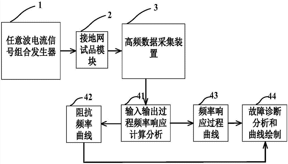
[0057] The technical problem solved by the present invention is to provide a substation grounding grid fault diagnosis method based on arbitrary current-voltage detection waveform frequency response analysis, that is, use an on-site arbitrary wave signal current generator to output a test signal current of a certain amplitude (> 10A, generally select 20A), applied to the ground down conductor of the substation grounding grid under evaluation, meas


PUM


Abstract

The invention relates to a fault diagnosis method and device for transformer station grounding network. The method comprises the following steps of: 1, selecting a grounding state parameter test pointof a specific grounding down lead of the transformer station grounding network; 2, connecting a field arbitrary wave current signal combination generator, selecting a representative grounding down lead at a different location of the grounding network as a voltage response output terminal, and connecting the voltage response output terminal to a high-frequency data acquisition device; 3, obtainingthe frequency response process curves of the representative grounding down leads at different locations of the grounding network; 4, subjecting the curves to the combined correlation coefficient analysis; and 5, evaluating the running status of the grounding network according to a result of the combined correlation coefficient analysis. Compared with the prior art, the fault diagnosis method hasthe advantages of ensuring the safe and reliable operation of a power system, being simple, accurate, and not limited by field operating conditions.

Description


Claims


Application Information

Patent Timeline
Owner SHANGHAI MUNICIPAL ELECTRIC POWER CO
Why Eureka
Try Eureka