Method for replacing oil inlet pipe of crane

A replacement method and crane technology, applied in metal processing, metal processing equipment, manufacturing tools, etc., can solve the problems that the joint body 1 is difficult to unscrew, reduce the replacement efficiency of the oil inlet pipe 4, and affect the replacement efficiency of the oil inlet pipe.

Active Publication Date: 2018-06-08
徐州天骋智能科技有限公司
View PDF6 Cites 1 Cited by
  • Summary
  • Abstract
  • Description
  • Claims
  • Application Information

AI Technical Summary

Benefits of technology

This technology allows for easy maintenance by replacing damaged parts without having to stop work from being done during repairs. One embodiment involves attaching both fixation blocks onto one end of an articulated arm called a joining member (joining head). These fixes help keep it securely connected when needed. Another version uses only one rotation motor instead of multiple motors at once but still works well if all these components have been properly adjusted correctly before they start working. Overall, this system makes repair faster than traditional methods while maintaining safety standards.

Problems solved by technology

This patented technical problem addressed by this patents relates to improving the maintenance or replacing efficiency of an oily liquid supply line that has been damaged due to damage caused during operation.

Method used


Image

  • Method for replacing oil inlet pipe of crane
  • Method for replacing oil inlet pipe of crane
  • Method for replacing oil inlet pipe of crane

Examples


Embodiment Construction

[0020] Further detailed explanation through specific implementation mode below:

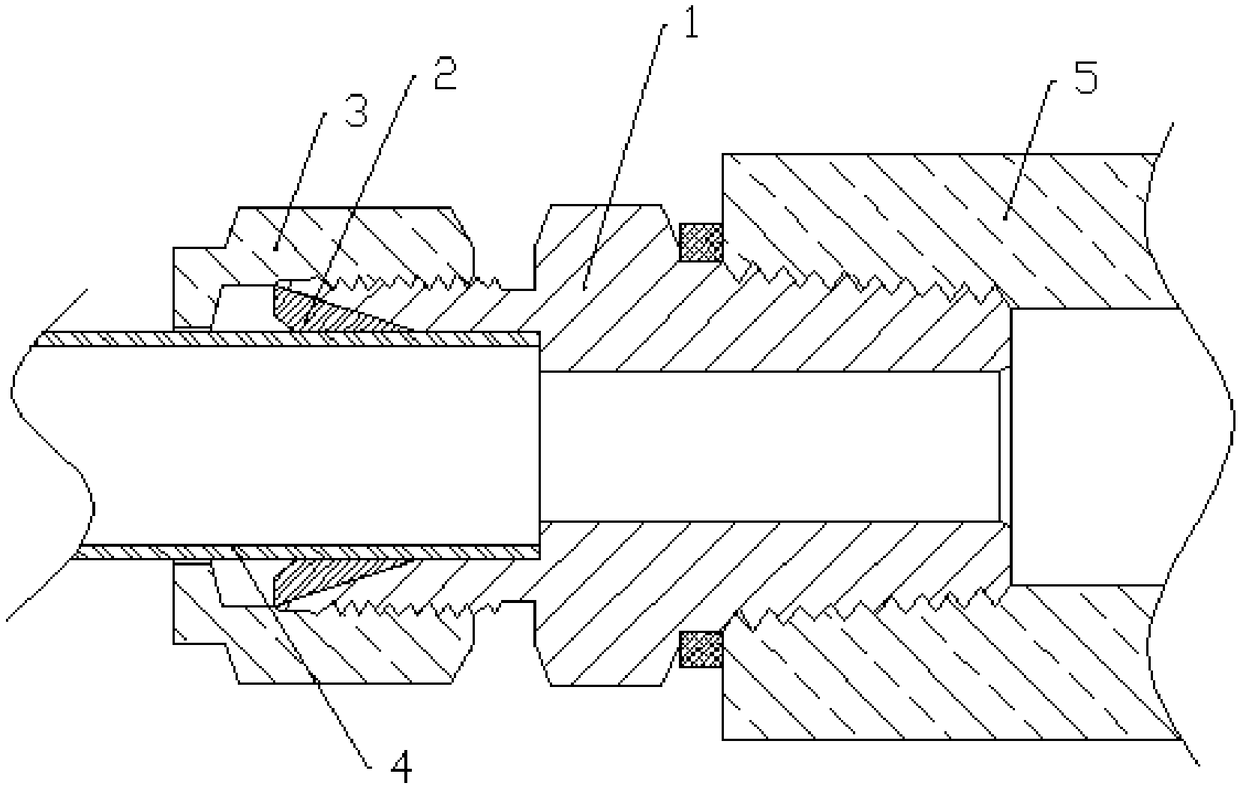
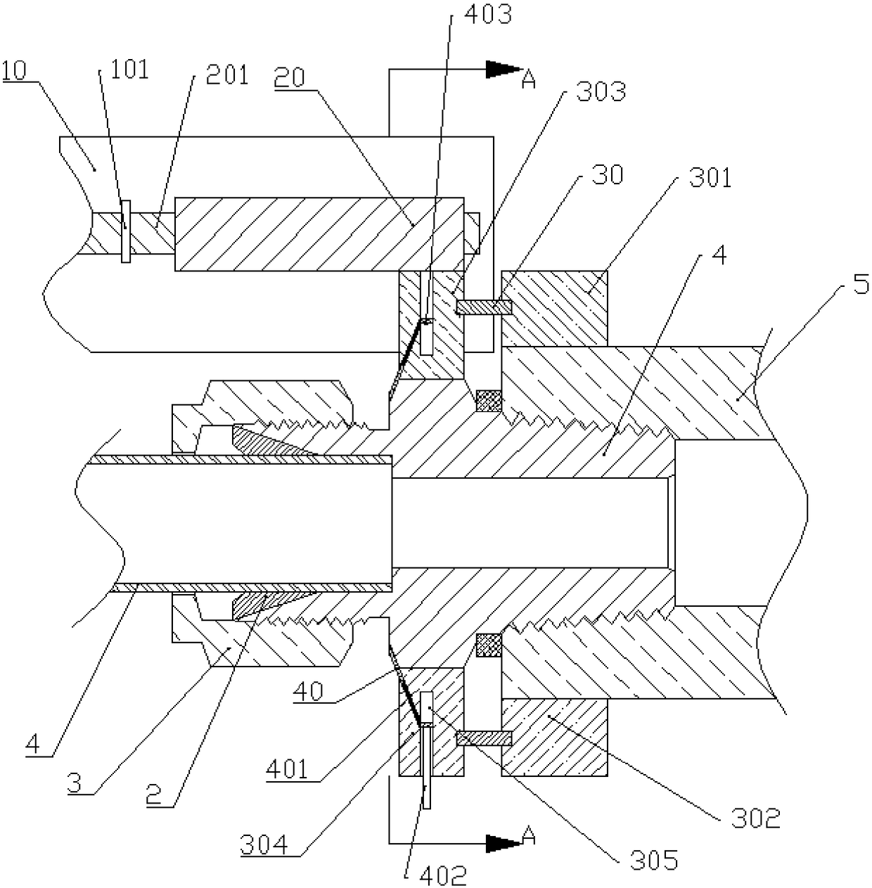
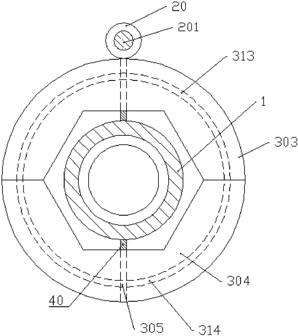
[0021] The reference signs in the accompanying drawings of the specification include: joint body 1, joint head 5, support frame 10, support ring 101, stud 20, screw rod 201, spring rod 30, first fixed block 301, first annular groove 311, second Two fixed blocks 302, the second annular groove 312, the first rotating block 303, the third annular groove 313, the second rotating block 304, the fourth annular groove 314, the vertical groove 305, the baffle plate 40, the pull bar 401, the insertion rod 402 . Skateboard 403 .

[0022] This method comprises the following steps:

[0023] Step 1: mark the joint body to be replaced on the crane as the first joint body 1; mark the joint body on the new oil inlet assembly as the second joint body 1.

[0024] Step 2: Prepare the replacement unit, basically as attached figure 2 , attached image 3 And attached Figure 4 As shown, it includes a support frame


PUM


Abstract

The invention relates to the field of crane maintenance methods, and particularly discloses a method for replacing an oil inlet pipe of a crane. According to the method, a detachable first fixed block, a detachable second fixed block, a detachable first rotating block and a detachable second rotating block are used, the first rotating block and the second rotating block can be matched with a powerunit so that a first joint body can be disassembled, a second joint body can also be assembled, and a damaged oil inlet pipe assembly in a crane system can be conveniently and quickly disassembled and assembled.

Description


Claims


Application Information

Patent Timeline
Owner 徐州天骋智能科技有限公司
Why Eureka
Try Eureka