Pavement marking device

A road marking and tank technology, applied in the field of marking machines, can solve problems such as troublesome use and waste of labor, and achieve the effects of convenient use, avoiding waste of labor, and simple structure

Inactive Publication Date: 2018-06-15
新昌县吉利标准件厂
View PDF0 Cites 0 Cited by
  • Summary
  • Abstract
  • Description
  • Claims
  • Application Information

AI Technical Summary

Benefits of technology

This patented technology allows for better control over how paint dots are applied during highway traffic signs by providing an improved way that makes them easier to see even underground without having to manually apply these marks every few hours or making sure they don't be mistakenly marked up next other areas instead of just being left behind. Additionally, there may have some lights attached around its edges where no markers could get out clearly visible from certain angles while still showing their shapes well enough to help operators identify them more easily.

Problems solved by technology

The technical problem addressed by this patented technology relates to improving the efficiency and accuracy of road markers during traffic control procedures for both civilian infrastructure projects such as streets or plaza areas. Current methods require manual operation involving multiple tools like an optical scope, lasers, etc., making them time-consuming and difficult to handle properly when working alongside existing equipment. This new solution proposes a way to automate these tasks without requiring any extra effort from workers who work alone.

Method used


Image

  • Pavement marking device
  • Pavement marking device

Examples


Embodiment Construction

[0015] The following will clearly and completely describe the technical solutions in the embodiments of the present invention with reference to the accompanying drawings in the embodiments of the present invention. Obviously, the described embodiments are only some, not all, embodiments of the present invention.

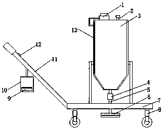
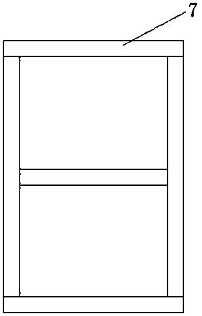
[0016] refer to Figure 1-2 , a road marking device, comprising a booster pump 1, a tank body 3, a discharge pipe 5, a base 7, a distance meter 9, a handle 11 and a heating plate 13, the side wall of the tank body 3 is hollow, and the inside of the side wall Heating sheet 13 is installed, tank body 3 is connected with the output end of booster pump 1, the bottom of tank body 3 is connected with spray brush head 6 through discharge pipe 5, and tank body 3 is fixed on the top of base 7 by bracket, and the outlet An electromagnetic valve 4 is installed on the material pipe 5, and the input end of the electromagnetic valve 4 is connected with a control switch 12 through a w


PUM


Abstract

The invention discloses a pavement marking device which comprises a booster pump, a tank body, a discharging pipe, a distance meter and a heating sheet. The side wall of the tank body is hollow, the heating sheet is installed in the side wall, the tank body is connected with the output end of the booster pump, the bottom of the tank body is connected with a spraying head through the discharging pipe, the tank body is fixed to the upper portion of a base through a support, an electromagnetic valve is installed on the discharging pipe, and the input end of the electromagnetic valve is connectedwith a control switch through a lead. The pavement spray type marking device is simple in structure and is mainly composed of the booster pump, the tank body and the spraying head, the spraying head of the device is located below the base, the device is provided with the base shaped like a Chinese character 'ri', due to the adoption of the base of the structure, when a worker conducts spraying marking operation, the shape of the sprayed marked line can be observed at any time, a disqualified marked line is prevented from being sprayed, and the situation that a traditional handheld spray devicewastes labor is avoided as well.

Description


Claims


Application Information

Patent Timeline
Owner 新昌县吉利标准件厂
Why Eureka
Try Eureka