Obstacle feature extraction method based on millimeter wave radar and laser radar

A millimeter-wave radar and lidar technology, which is used in the re-radiation of electromagnetic waves, the reflection/re-radiation of radio waves, and character and pattern recognition. The effect of increasing the processing speed and ensuring safe driving

Inactive Publication Date: 2018-09-07
TIANJIN UNIV
View PDF10 Cites 35 Cited by
  • Summary
  • Abstract
  • Description
  • Claims
  • Application Information

AI Technical Summary

Benefits of technology

This technology improves upon previous methods that only use one type of sensor but it prevents interference from other types without compromising its accuracy or reliance on certain features like edges. It also simplifies calculations needed when combining different sources of data together. Overall, this innovation helps improve safety measures during autonomous vehicle operation while reducing computational complexity.

Problems solved by technology

This patented technical problem addressed in this patents relates to improving the efficiency and reliability of autonomously driven cars' surroundings monitoring systems (CWS). Current solutions involve utilizing different types of sensors or combining their outputs into one signal processor. These techniques have limitations due to factors like rain/fogging conditions and limited visibility under various lighting scenarios. Therefore, an improved solution needs to be developed that overcomes these issues while still maintaining accurate environmental perceptual recognition capabilities.

Method used


Image

  • Obstacle feature extraction method based on millimeter wave radar and laser radar
  • Obstacle feature extraction method based on millimeter wave radar and laser radar
  • Obstacle feature extraction method based on millimeter wave radar and laser radar

Examples


Embodiment Construction

[0045] In order to make the objectives, technical solutions and advantages of the embodiments of the present invention clearer, the technical solutions of the present invention will be clearly and completely described below in conjunction with the accompanying drawings.

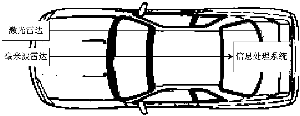
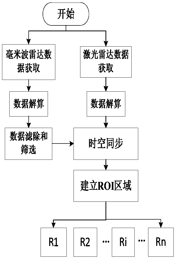
[0046] Step 1. Obtain the raw data of millimeter-wave radar and lidar radar;

[0047]The millimeter-wave radar data is transmitted to the industrial computer through the CAN (Control Area Network) bus, and the update cycle is 50ms; the lidar data is transmitted to the industrial computer through the Ethernet interface; the update cycle is 40ms.

[0048] Step 2. Calculate the raw radar data to obtain obstacle position information;

[0049] After the radar raw data is obtained through step 1, according to the millimeter-wave radar and lidar protocol, the data calculation of the millimeter-wave radar and lidar is respectively realized through computer programming;

[0050] Step 3. Filter the data after the millime


PUM


Abstract

The invention discloses an obstacle feature extraction method based on a millimeter wave radar and a laser radar. The method includes the following steps that: step 1, radar raw data are acquired; step 2, the radar original data are solved according to a radar protocol, so that obstacle position information can be obtained; step 3, the solved millimeter wave radar data are screened; step 4, time and space synchronization is performed on the millimeter wave radar and the laser radar; step 5, regions of interest (ROI) are established in a laser radar coordinate system according to millimeter wave radar information and are denoted as Ri, wherein i is equal to 1, 2, ... n, wherein n is the number of the effective targets of the millimeter wave radar; step 6, the point cloud data of the i-th ROI are processed according to a scattered point cloud data simplification processing method; and step 7, a two-dimensional image is generated on the basis of the point cloud data, edge detection is performed on the image, and obstacle features are extracted. With the method adopted, obstacle edge information can be obtained, and therefore, more references can be provided for a driverless decision-making layer.

Description


Claims


Application Information

Patent Timeline
Owner TIANJIN UNIV
Why Eureka
Try Eureka