Method for improving harness winding efficiency in textile process

A wire harness and textile technology, which is applied in the field of improving wire harness winding efficiency, can solve the problems of increasing labor force and production costs, and achieve the effects of saving labor force, uniform winding, and improving wire harness winding efficiency

Active Publication Date: 2018-09-14
绍兴柯桥惠樊绣品有限公司
View PDF6 Cites 0 Cited by
  • Summary
  • Abstract
  • Description
  • Claims
  • Application Information

AI Technical Summary

Problems solved by technology

[0003] However, the traditional winding machine for textile needs another processing procedure to wind the wire harness to the surface of the bobbin, and

Method used


Image

  • Method for improving harness winding efficiency in textile process
  • Method for improving harness winding efficiency in textile process
  • Method for improving harness winding efficiency in textile process

Examples


Embodiment Construction

[0034] In order to make the technical means, creative features, goals and effects achieved by the present invention easy to understand, the present invention will be further described below in conjunction with specific embodiments.

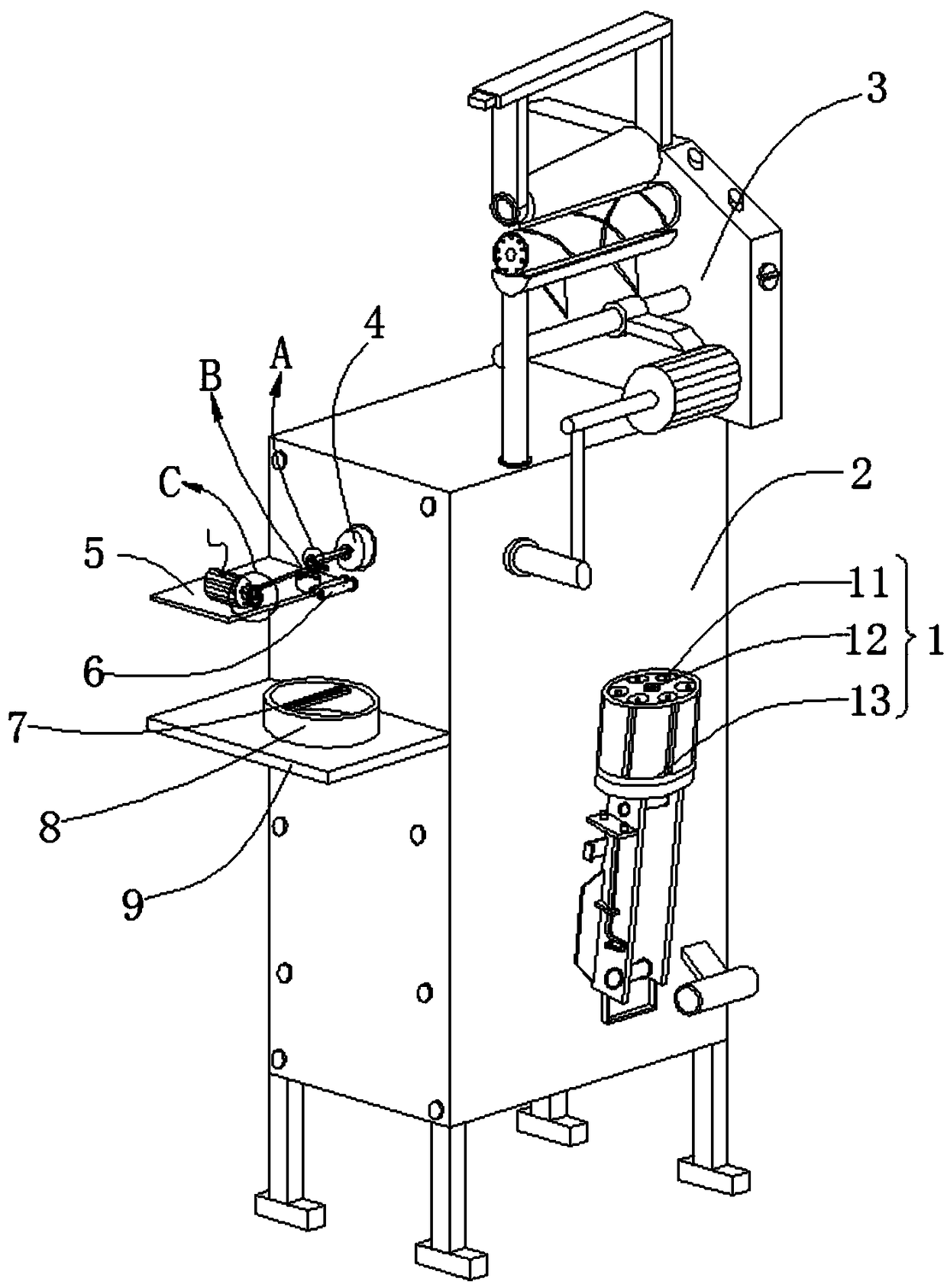
[0035] likefigure 1 As shown, a method for improving wire harness winding efficiency in a weaving process of the present invention, the method includes the following steps:

[0036] S1: Put the yarn on the winder;

[0037] S2: winding the yarn in S1;

[0038] S3: conveying the yarn in S2 to the next process for spinning;

[0039] Wherein, the winding machine used in this method includes a wire-feeding mechanism 1, a housing 2, a body 3, a first motor 4, a first support plate 5, two limit posts 6, a sliding mechanism 7, a wire box 8, a second Support plate 9, driving mechanism 9a, wire take-up mechanism 9b and wire pushing mechanism 9c; The top of described casing 2 is installed for the described body 3 of winding, and the side of described casing 3


PUM


Abstract

The invention relates to the field of textiles, in particular to a method for improving the harness winding efficiency in the textile process. The method comprises steps of S1 to S3. A winding machineadopted in the method comprises a pay-off mechanism, a shell, a machine body, a first motor, a first supporting plate, limiting columns, a sliding mechanism, a harness box, a second supporting plate,a drive mechanism, a take-up mechanism and a harness pushing mechanism. A triangular prism-shaped fixing column located in the pay-off mechanism and a clamping column of the take-up mechanism are equal in size, a bobbin can be directly clamped to the surface of the fixing column, the drive mechanism coordinates with the harness pushing mechanism to enable a harness needing to be wound to swing between the two limiting columns, the situation that the harness is taken up at one position of the surface of the bobbin is avoided, taking up is more uniform, the harness box is internally and fixedlyconnected with a sliding frame, the sliding frame is internally connected with a swinging block which is of a T-shaped structure in a sliding manner, the harness needing to be wound penetrates a harness hole located in the swinging block, a spring is arranged between the swinging block and the sliding frame and coordinates with the swinging of the harness pushing mechanism, and harness snapping from tension is avoided.

Description


Claims


Application Information

Patent Timeline
Owner 绍兴柯桥惠樊绣品有限公司
Why Eureka
Try Eureka