Track mobile type friction stir welding equipment

A friction stir and welding equipment technology, applied in welding equipment, welding equipment, auxiliary welding equipment, etc., can solve the problems of reduced service life of the friction head, and achieve the effects of easy replacement, improved utilization rate, and convenient operation

Inactive Publication Date: 2018-11-13
HUNAN UNIV OF ARTS & SCI
View PDF5 Cites 2 Cited by
  • Summary
  • Abstract
  • Description
  • Claims
  • Application Information

AI Technical Summary

Benefits of technology

This invention relates to an apparatus used during robotic arm movements that allows it move around freely without being restricted or affected from its surroundings. It uses multiple types of tools like screwdrivers, motors and sensory devices attached on different platforms called turntables. These machines are designed to work together smoothly while also allowing them to rotate and slide about their own axis. They have various features such as lubricating oil sprayers at one end, water supply systems near the other ends, heat dissipators along the way, and filters to protect these components against damage caused due to high temperatures. Overall, this technology improves efficiency and productivity when moving objects through space.

Problems solved by technology

This patented technical solution describes how different materials can get mixed together when they rub against each other during frictional joining processes such as wire fusion or laser beam melting (LF). These techniques require that certain surfaces have very good heat dissipation properties while also being able to rotate quickly without getting damaged due to their rapid movement over these surfaces.

Method used


Image

  • Track mobile type friction stir welding equipment
  • Track mobile type friction stir welding equipment
  • Track mobile type friction stir welding equipment

Examples


Embodiment Construction

[0028] The following will clearly and completely describe the technical solutions in the embodiments of the present invention with reference to the accompanying drawings in the embodiments of the present invention. Obviously, the described embodiments are only some, not all, embodiments of the present invention. Based on the embodiments of the present invention, all other embodiments obtained by persons of ordinary skill in the art without making creative efforts belong to the protection scope of the present invention.

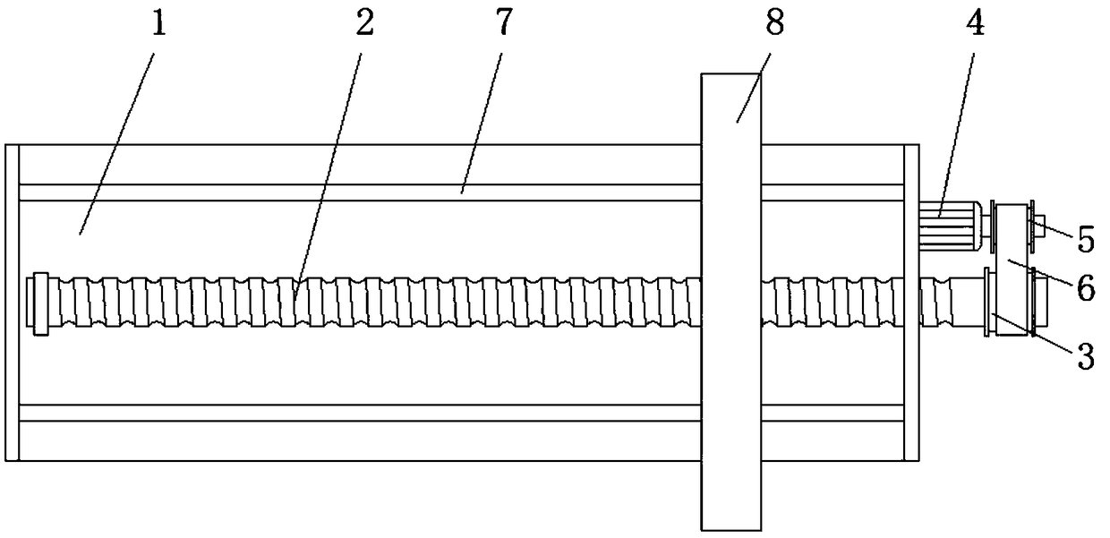
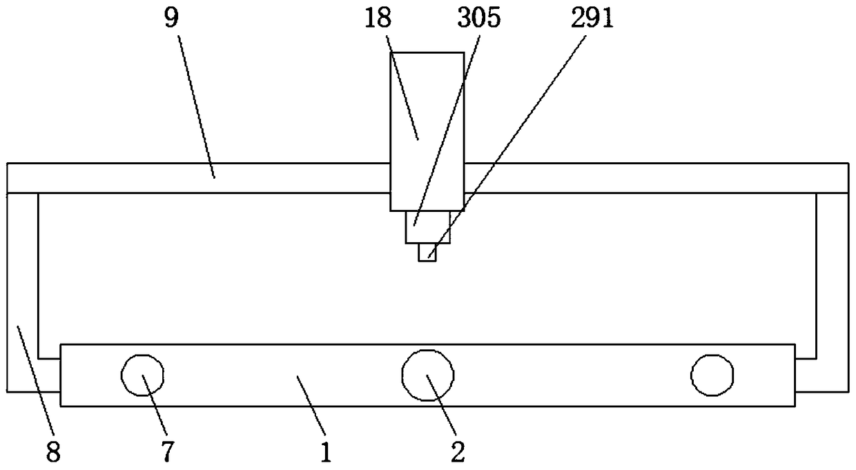
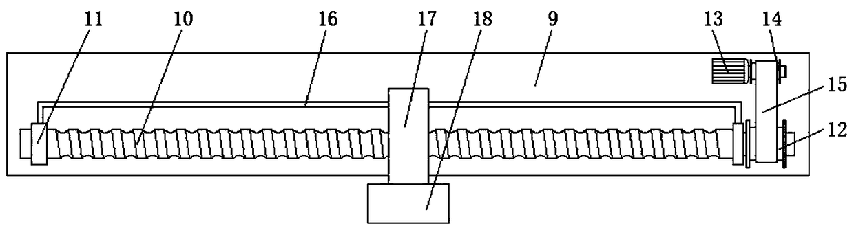
[0029] see Figure 1-6, an orbital mobile friction stir welding equipment, including a workbench 1, a first screw 2 is movable inside the front of the workbench 1, and one end of the first screw 2 extends to the outside of one side of the workbench 1 and is fixedly set with The first roller 3, one side of the first roller 3 is fixedly installed with the first motor 4 on the side of the workbench 1, the model of the first motor 4 is Y132S2-2, and the outer wall of


PUM


Abstract

The invention relates to the technical field of friction welding equipment, and discloses track mobile type friction stir welding equipment. The track mobile type friction stir welding equipment includes a workbench; a first screw rod is movably mounted in the front face of the workbench in a sleeving mode, one end of the first screw rod extends to the exterior of one side of the workbench, and afirst roller is mounted at one end of the first screw rod in a sleeving mode; and a first motor located on one side of the workbench is fixedly mounted on one side of the first roller, a second rolleris fixedly mounted on the outer wall of an output shaft of the first motor in a sleeving mode, the outer wall of the second roller is in transmission connection with the outer wall of the first roller through a first belt, and a first sleeve rod located in the workbench is arranged above the first screw rod. The track mobile type friction stir welding equipment can be rotated and in friction withthe machined parts by arranging a friction head, a mounting plate, a sleeve plate, a servo motor and an isolation box, and meanwhile, the servo motor and the sleeve plate are arranged in a sleeved mode to achieve the function of facilitating the replacement of the friction head.

Description


Claims


Application Information

Patent Timeline
Owner HUNAN UNIV OF ARTS & SCI
Why Eureka
Try Eureka