Combined lock nut

An anti-loosening nut, combined technology, applied in the direction of nuts, screws, bolts, etc., can solve the problems of parts or equipment damage, safety accidents, limited use conditions, inability to be widely used, etc., to achieve increased friction, good sealing effect, Good anti-loosening effect

Inactive Publication Date: 2018-11-13
董尊久
View PDF0 Cites 5 Cited by
  • Summary
  • Abstract
  • Description
  • Claims
  • Application Information

AI Technical Summary

Benefits of technology

This patented technology allows for better securement by reducing slippage or separation during assembly compared with traditional methods like screws that require excessive torquings. It also prevents rustiness caused by moisture ingress into the combination nut's interior through its spline groove joint system. Additionally, it uses an elastic material called leather instead of metal to create a strong bond around both parts while still allowing them to slide freely within one another. Overall, this design improves overall performance and durability over existing solutions.

Problems solved by technology

This patented technical problem addressed in this patents relates to improving the durability and reliance on quick connectors that can withstand strong vibrations caused by heavy machines such as construction workers.

Method used


Image

  • Combined lock nut
  • Combined lock nut
  • Combined lock nut

Examples


Embodiment Construction

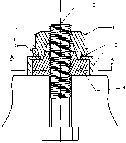
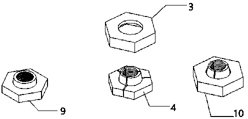
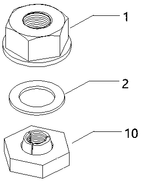
[0023] Such as figure 1 and image 3 As shown, a combined locknut includes a lock nut 1 , a rubber washer 2 and a combined nut 10 . There is a concave round table 7 inside one end of the lock nut 1, and a flange surface 5 outside; the three split nuts 4 of the combined nut 10 are placed in the support sleeve 3 according to the corresponding sequence on the convex nut 9 before being divided, The rotation directions of the threads of each split nut 4 are the same, and there are equal circumferential gaps 11 between every two split nuts 4 , and the split nuts 4 can only Produce the radial displacement along bolt 8; Because the taper of lock nut concave round table 7 is identical with the taper of the convex round table of convex nut 9, so the inner surface of lock nut concave round table 7 and the outer surface of split nut convex table 6 can coincide.

[0024] When assembling, install the combination nut 10 first, then place the rubber gasket 2, and finally install the lock nut


PUM


Abstract

The invention discloses a combined lock nut. The combined lock nut comprises lock nut body, a combined nut body and a rubber gasket. When the combined lock nut is assembled and screwed, a concave circular truncated cone of the lock nut body squeezes a convex circular truncated cone of a split-type nut body in the combined nut body, the split-type nut body is stressed to move in the radial direction of a bolt, then a threaded mesh clearance between the bolt and the split-type nut body is eliminated, and an internal thread of the split-type nut body and an external thread of the bolt are engagedand locked in a clearance-free mode; and meanwhile, under the effect of the pre-tightening force of the lock nut body, the friction force between the split-type nut body in the combined nut body andthe external thread in the bolt is increased, so that unscrewing and looseness, caused by vibration, of spirals are effectively prevented, and good fastening and locking effects are achieved.

Description


Claims


Application Information

Patent Timeline
Owner 董尊久
Why Eureka
Try Eureka