Water chilling unit provided with super-cooler and lubricating oil cooler

A chiller and lubricating oil technology, which is applied in refrigerators, refrigeration components, refrigeration and liquefaction, etc., can solve problems such as excessive lubricating oil temperature, abnormal operation of expansion valves, and large space occupied by condensers, so as to improve temperature accuracy, Good supercooling effect and good cooling effect

Pending Publication Date: 2018-11-13
ANHUI MELUCK REFRIGERATION EQUIP
View PDF1 Cites 1 Cited by
  • Summary
  • Abstract
  • Description
  • Claims
  • Application Information

AI Technical Summary

Problems solved by technology

However, the method of increasing the heat exchange area of ​​the condenser takes up a lot of space, the economy is not good, and it is impossible to accurately control the degree of subcooling
[0004] For high-power units, it is necessary to cool the lubricating oil to prevent the temperature of the lubricating oil from being too high and the viscosity to drop, resulting in poor lubrication of the compres

Method used


Image

  • Water chilling unit provided with super-cooler and lubricating oil cooler
  • Water chilling unit provided with super-cooler and lubricating oil cooler
  • Water chilling unit provided with super-cooler and lubricating oil cooler

Examples


Embodiment Construction

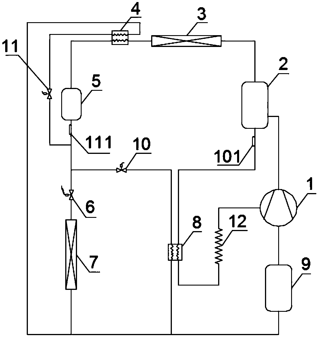
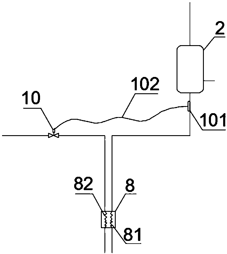
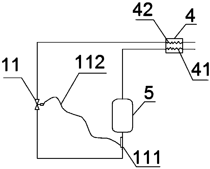
[0024] see figure 1 , figure 2 , image 3 with Figure 4 , the water chiller provided with subcooler and lubricating oil cooler in this embodiment includes compressor module 1, condenser 3 and evaporator 7; the chiller also includes: oil separator 2, subcooler 4, liquid storage device 5, thermal expansion valve 6, lubricating oil cooler 8, gas-liquid separator 9, and a first control valve 10 and a second control valve 11 with auxiliary control functions.

[0025] Such as figure 1 As shown, an oil separator 2 is arranged at the outlet end of the compressor module 1, and the refrigerant gas outlet end of the oil separator 2 is sequentially connected to the condenser 3, the subcooler cooling passage 41 of the subcooler 4, and the liquid accumulator 5 , thermal expansion valve 6, evaporator 7, gas-liquid separator 9, and return to the suction end of the compressor module 1, constituting the main passage of the chiller.

[0026] figure 1 Also shown in the figure: between the ou


PUM


Abstract

The invention discloses a water chilling unit provided with a super-cooler and a lubricating oil cooler. A main loop of the water chilling unit is sequentially connected with a compressor module, an oil separator, a condenser, the super-cooler, a liquid storing machine, a thermal expansion valve, an evaporator, an air and liquid separator and the like. A first bypass and a second bypass are correspondingly arranged in parallel between the outlet of the liquid storing machine and the outlet of the evaporator; super-cooling of condensate of a refrigerant and cooling of lubricating oil are realized; the evaporation temperature of the water chilling unit and the oil supply temperature of a compressor are precisely controlled; the lubrication performance of the compressor of key equipment is improved; and the environmental suitability and reliability of the water chilling unit are improved.

Description


Claims


Application Information

Patent Timeline
Owner ANHUI MELUCK REFRIGERATION EQUIP
Why Eureka
Try Eureka