Moving mechanism of numerical control machine tool and lubricating method thereof

A technology of moving mechanism and numerically controlled machine tools, applied in the field of machine tools, which can solve problems such as the inability to automatically switch between lubricating fluids, uneven addition of lubricating fluids, and inability to ensure stable work, etc., and achieve the effects of wide application range, stable work, and labor saving

Active Publication Date: 2021-05-28
浙江赫科智能装备有限公司
View PDF7 Cites 0 Cited by
  • Summary
  • Abstract
  • Description
  • Claims
  • Application Information

AI Technical Summary

Problems solved by technology

[0004] Second, the addition of lubricating fluid is not uniform enough, which will cause the column to tilt when moving. At the same time, in order to ensure that all parts are lubricated, a large amount of lubricating fluid is usually wasted, and most of the lubricating fluid is redundant. Generally, it is wasted and flowed out, which increases the cost ;
[0005] Third, there are many kinds of lubricating fluids, most of which will change their properties according to different environments such as temperature and humidity (for example, the demulsification ability of general lubricat

Method used


Image

  • Moving mechanism of numerical control machine tool and lubricating method thereof
  • Moving mechanism of numerical control machine tool and lubricating method thereof
  • Moving mechanism of numerical control machine tool and lubricating method thereof

Examples


Embodiment 1

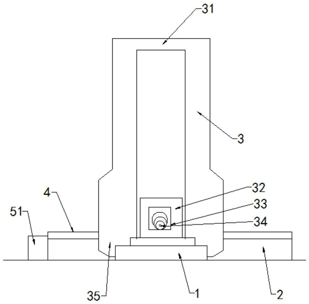
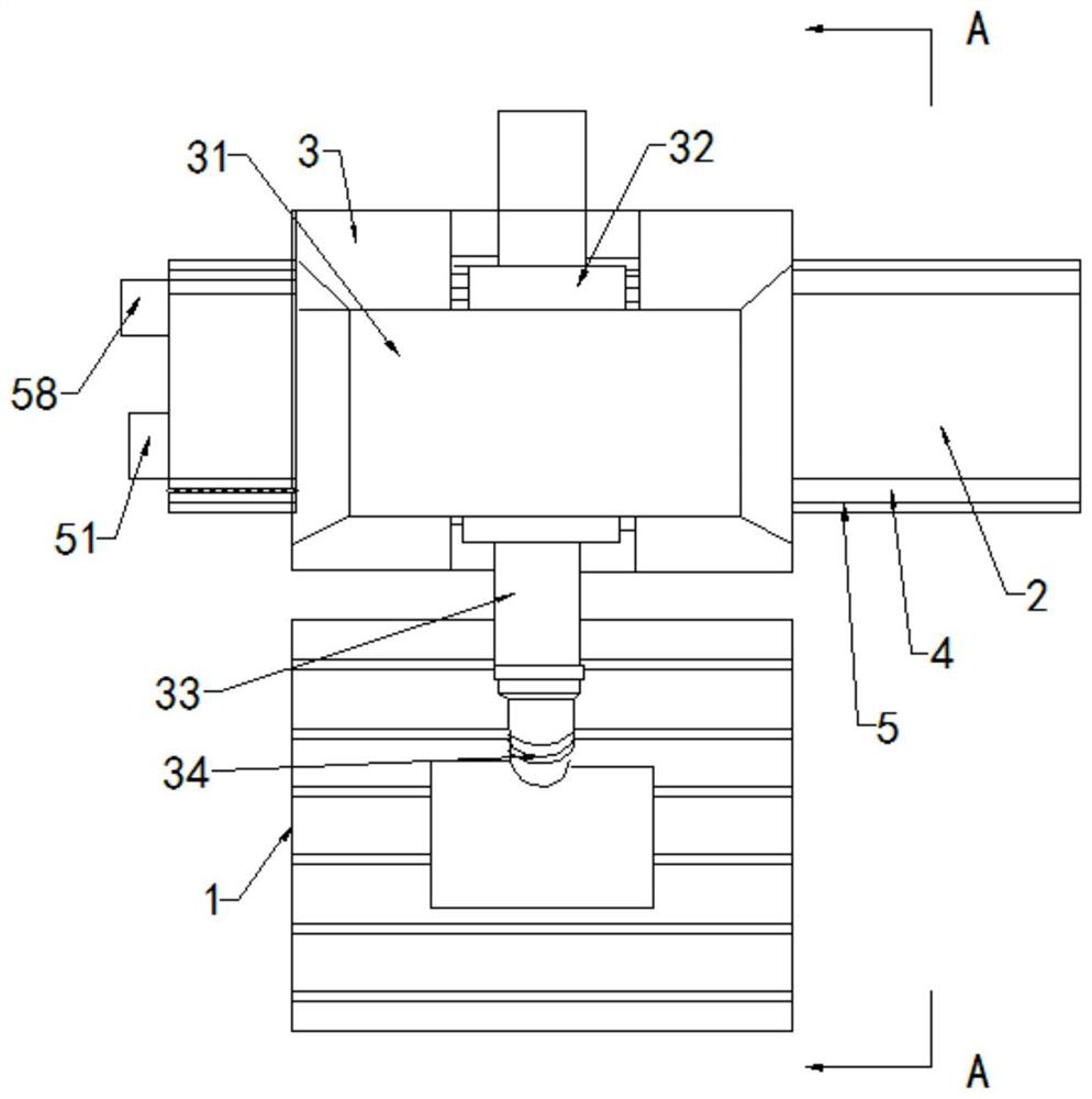
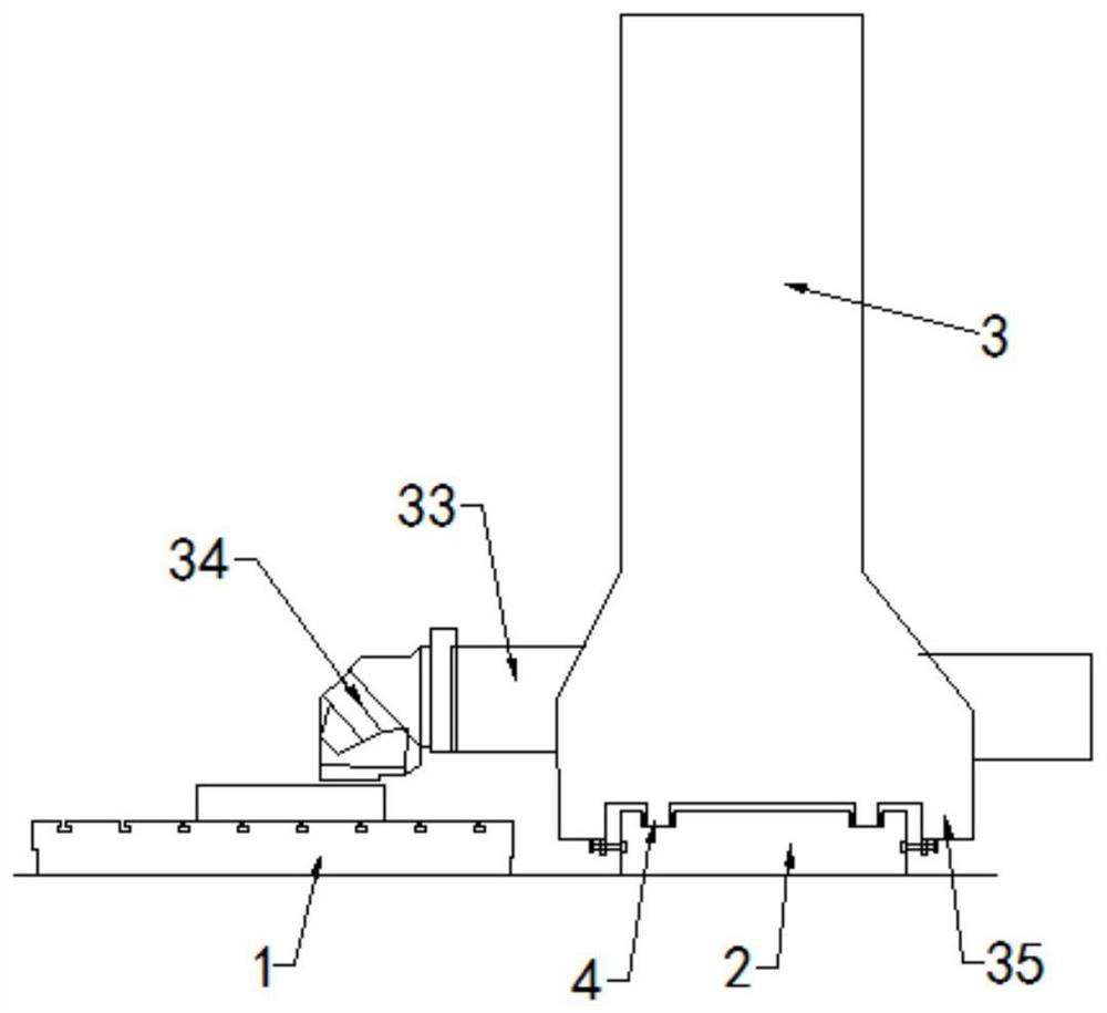
[0039] Such as Figure 1 to Figure 5 As shown, the present invention discloses a moving mechanism of a numerical control machine tool. In a specific embodiment of the present invention, it includes a workbench 1 and a base 2 fixed on the ground, and the base 2 is provided with a column that can slide along it. 3. The column 3 is slidably arranged on the base 2 through the sliding mechanism 4; the column 3 is two, and the upper ends of the two columns 3 are integrally formed by welding the beam 31, and the inner walls of the two columns 3 are provided with movable The slide block 32 that slides vertically on the inner side wall of the column 3 includes a drive mechanism that controls the slide block to move up and down and a drive mechanism that controls the column to move on the base in this embodiment (the drive mechanism is a transmission technology so no more details here. description), one end of the slider 32 is fixed with a slider 33, and the slider 33 can move axially rela

Embodiment 2

[0047] Such as Figure 8 and Figure 9 As shown, the difference between this embodiment and the above-mentioned embodiments is that in this embodiment, several oil storage units 6 are evenly opened on the bottom of the sliding groove 42, and each oil storage unit 6 includes a first oil storage tank 61 and a first oil storage tank 61. The second oil storage tank 62, the first oil storage tank 61 and the second oil storage tank 62 are circular tanks, the first oil storage tank 61 and the second oil storage tank 62 are concentrically arranged, and the diameter of the first oil storage tank 61 It is larger than the second oil storage groove 62; the bottom of the sliding groove 42 is also provided with a first flow groove 63 and a second flow groove 64, and the first flow groove 63 is located at the first oil storage groove 61 and the second oil storage groove 62 Between, the first flow groove is evenly arranged around the circumference of the second oil storage groove, the first flo


PUM


Abstract

The invention provides a moving mechanism of a numerical control machine tool. According to the technical scheme, the moving mechanism of the numerical control machine tool is characterized by comprising a workbench and a base; two stand columns capable of sliding along the base are arranged on the base; the stand columns are arranged on the base in a sliding mode through sliding mechanisms; the upper ends of the two stand columns are fixedly connected through a cross beam; sliding blocks capable of vertically sliding on the opposite inner side walls of the stand columns are arranged on the inner side walls of the two stand columns; a sliding base is fixed to one ends of the sliding blocks; the sliding base can axially move relative to the sliding blocks in the direction perpendicular to the axis of the base; a tool head is installed at the end, away from the sliding blocks, of the sliding base; a connecting beam is arranged on the side edge of the base; the connecting beam is connected with the bottoms of the two stand columns; andthe base is further provided with a lubricating mechanism used for adding lubricating liquid to the sliding mechanism. The moving mechanism has the beneficial effects that oil is automatically supplied for lubrication, the lubricating liquid is uniformly added, and the lubricating liquid can be switched for lubrication work.

Description


Claims


Application Information

Patent Timeline
Owner 浙江赫科智能装备有限公司
Why Eureka
Try Eureka