Electrostatic spraying finished product drying device

An electrostatic spraying and drying device technology, which is applied to devices for coating liquids on surfaces, coatings, pretreatment surfaces, etc., can solve the problems of high use limitations, low reliability of use, and influence on drying effects, and achieve the limitations of use. Low performance, high practicability, and the effect of ensuring drying effect

Inactive Publication Date: 2018-11-20
太仓市联华静电喷涂厂(普通合伙)
View PDF0 Cites 0 Cited by
  • Summary
  • Abstract
  • Description
  • Claims
  • Application Information

AI Technical Summary

Benefits of technology

This new technology allows for better flexibility when driving multiple tools on different directions while also ensuring that all parts are being worked properly during rotation. It achieves this through an improved design where there's no moving part inside or outside it. Additionally, the system includes features like a limited space between two components called a partition board, which helps prevent water from getting into certain areas within the machine. Overall, these technical improvements improve efficiency and productivity.

Problems solved by technology

This patented technical problem addressed by this patents relates to an improved method for drying electrically charged dust particles during manufacturing processes such as elecrolithography (EPL). Current methods have limitations due to their lack of flexibility and adaptable options.

Method used


Image

  • Electrostatic spraying finished product drying device
  • Electrostatic spraying finished product drying device
  • Electrostatic spraying finished product drying device

Examples


Embodiment Construction

[0018] The specific implementation manners of the present invention will be further described in detail below in conjunction with the accompanying drawings and embodiments. The following examples are used to illustrate the present invention, but are not intended to limit the scope of the present invention.

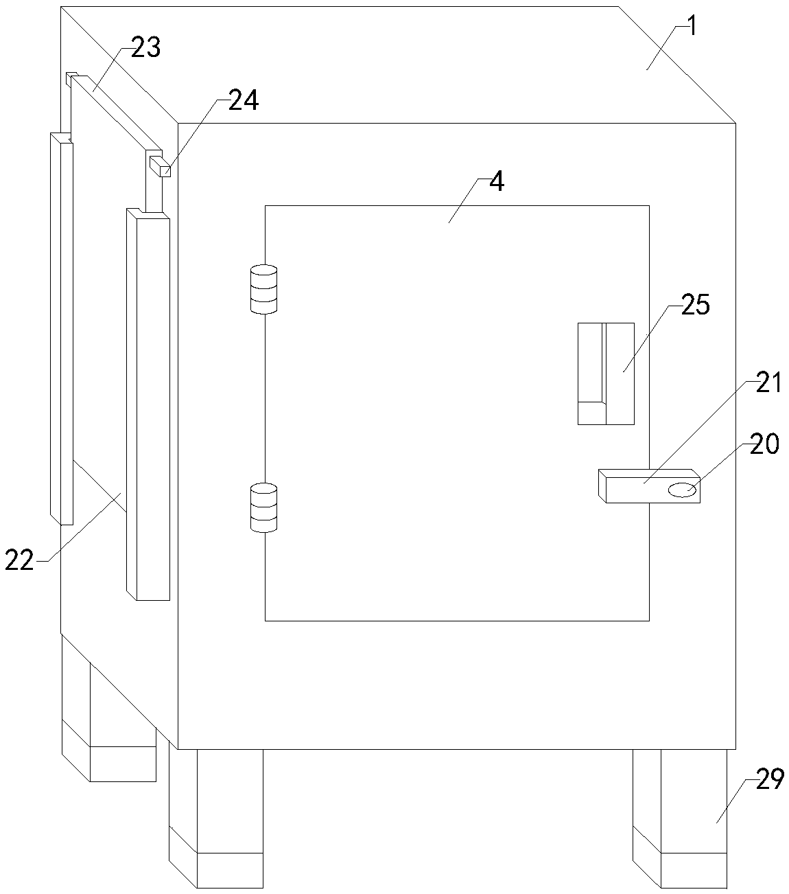
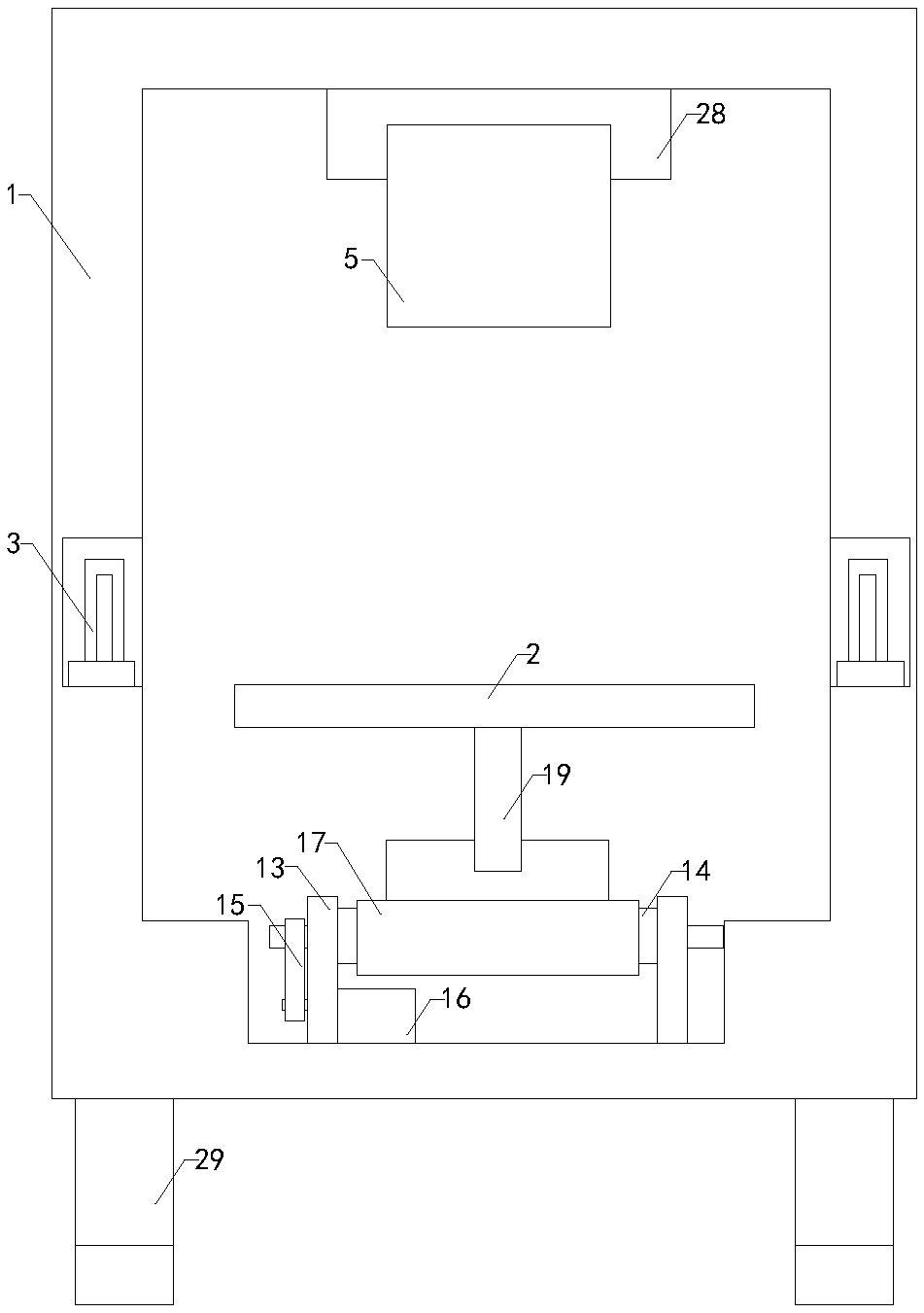
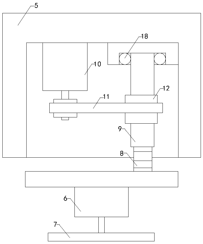
[0019] like Figure 1 to Figure 4 As shown, a drying device for electrostatic spraying finished products of the present invention includes a chassis 1, a support plate 2, two sets of electric heating rods 3 and a baffle 4, a working chamber is arranged in the chassis, and a pick-and-place opening is arranged at the front end of the body, and The pick-and-place opening communicates with the working chamber, and the side wall of the baffle is hinged to the side wall of the pick-and-place mouth. The left and right walls of the working chamber are respectively provided with two sets of card slots. In the card group slot; the working cavity is provided with a shrink frame 5, and


PUM


Abstract

The invention relates to the technical field of electrostatic spraying processing accessory devices, in particular to an electrostatic spraying finished product drying device. The working mode is relatively flexible, the use limitation is lower, the work is more uniform, and the practicality is higher; and in addition, the sealing of a machine box is higher, the drying effect is ensured, and the use effect is higher, so that the use reliability of the electrostatic spraying finished product drying device is improved. The electrostatic spraying finished product drying device comprises the machine box, a supporting plate, two sets of electrical heating bars and a baffle, further comprises a drive motor, a clamping plate, a threaded rod, a threaded pipe, a first servo motor, a chain, a firstchain wheel, a second chain wheel, two sets of front fixing frames, two sets of rear fixing frames, two sets of transmission rollers, a drive belt, a second servo motor and a conveyor belt, and further comprises a fixed shaft and a limiting plate. A working cavity is formed in the machine box, and the two sets of electrical heating bars are separately installed in two sets of clamping grooves. Theworking cavity is internally provided with a contraction frame. An installation plate is arranged in a contraction groove, the chain is arranged on the first chain wheel and the second chain wheel ina sleeving mode, a driven plate is arranged on the conveyor belt, and a rotating shaft is arranged in a rotating hole.

Description


Claims


Application Information

Patent Timeline
Owner 太仓市联华静电喷涂厂(普通合伙)
Why Eureka
Try Eureka