Pump-free supercharging process system and use method thereof
A process system and pressurized tank technology, applied in the direction of container filling method, container discharge method, pressure vessel, etc., can solve the problems that the commercial application field is still blank, so as to eliminate the risk of dangerous gas leakage, reduce costs, prolong The effect of running time
- Summary
- Abstract
- Description
- Claims
- Application Information
AI Technical Summary
Problems solved by technology
Method used
Image

Examples
Embodiment 1
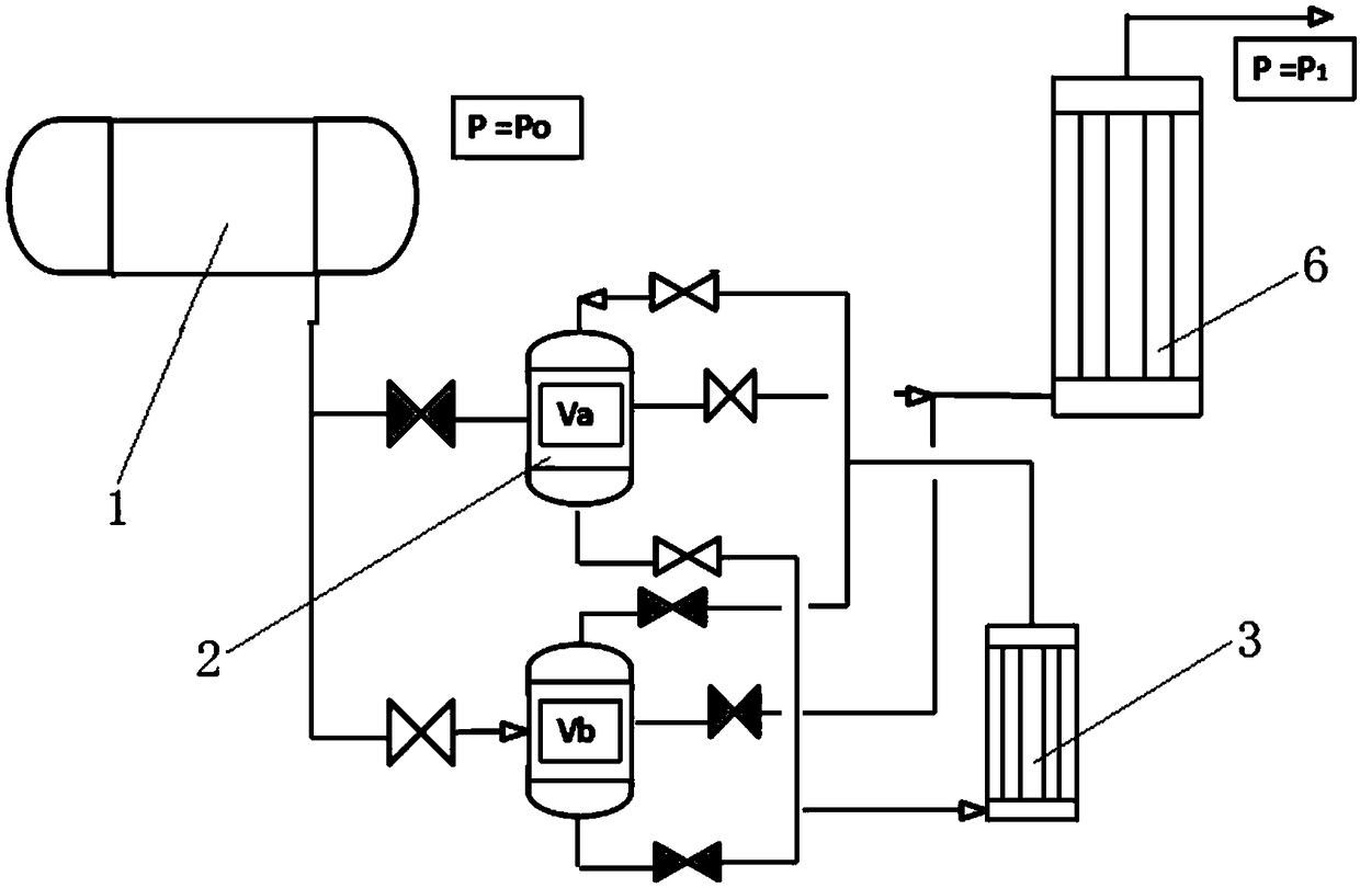
[0059] A pumpless pressurization process system in this embodiment includes an LNG storage tank 1, a booster tank 2, a booster unit 3, a liquid phase pipeline, a gas phase pipeline, a control valve, and a safety valve. The booster tank 2 is connected in parallel with two One, respectively the first booster tank and the second booster tank, the first input end of the first booster tank and the first input end of the second booster tank are connected with the LNG storage tank 1, the first booster tank Both the first output end of the first booster tank and the first output end of the second booster tank are connected to the input end of the booster unit, and the second input end of the first booster tank and the second input end of the second booster tank are connected to the booster unit. The output end of the pressure unit is connected, the second output end of the first booster tank and the second output end of the second booster tank are connected with the vaporizer 6 of the out
Embodiment 2
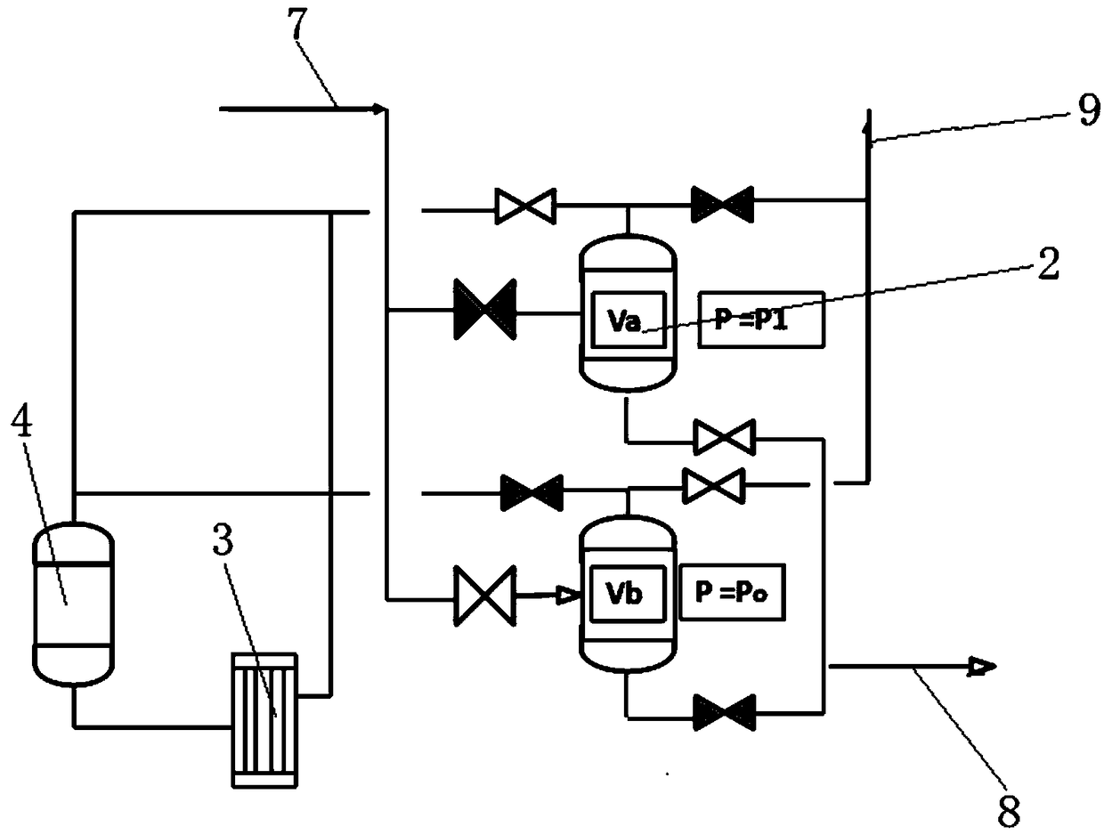
[0073] A pumpless pressurization process system of the present embodiment comprises an LNG inlet 7, two sets of parallel booster tanks 2, an LNG outlet 8, a gas vent 9, a booster unit 3 and an inert liquid storage tank 4, the booster tank The first input end of 2 is connected to the LNG inlet 7; the first output end of the booster tank 2 is connected to the LNG outlet 8; the second input end of the booster tank 2 is connected to the output end of the booster unit 3, and the output end of the booster unit 3 is also connected to The input end of the inert liquid storage tank 4; the input end of the booster unit 3 is connected to the output end of the inert liquid storage tank 4; the second input end of the booster tank 2 is also connected to the gas vent 9.
[0074] The inert gas pressurization system is added, and the inert gas is used to push the cryogenic liquid out to achieve rapid pressure increase, without waiting for the process of equilibrium between the pressurized gas and
Embodiment 3
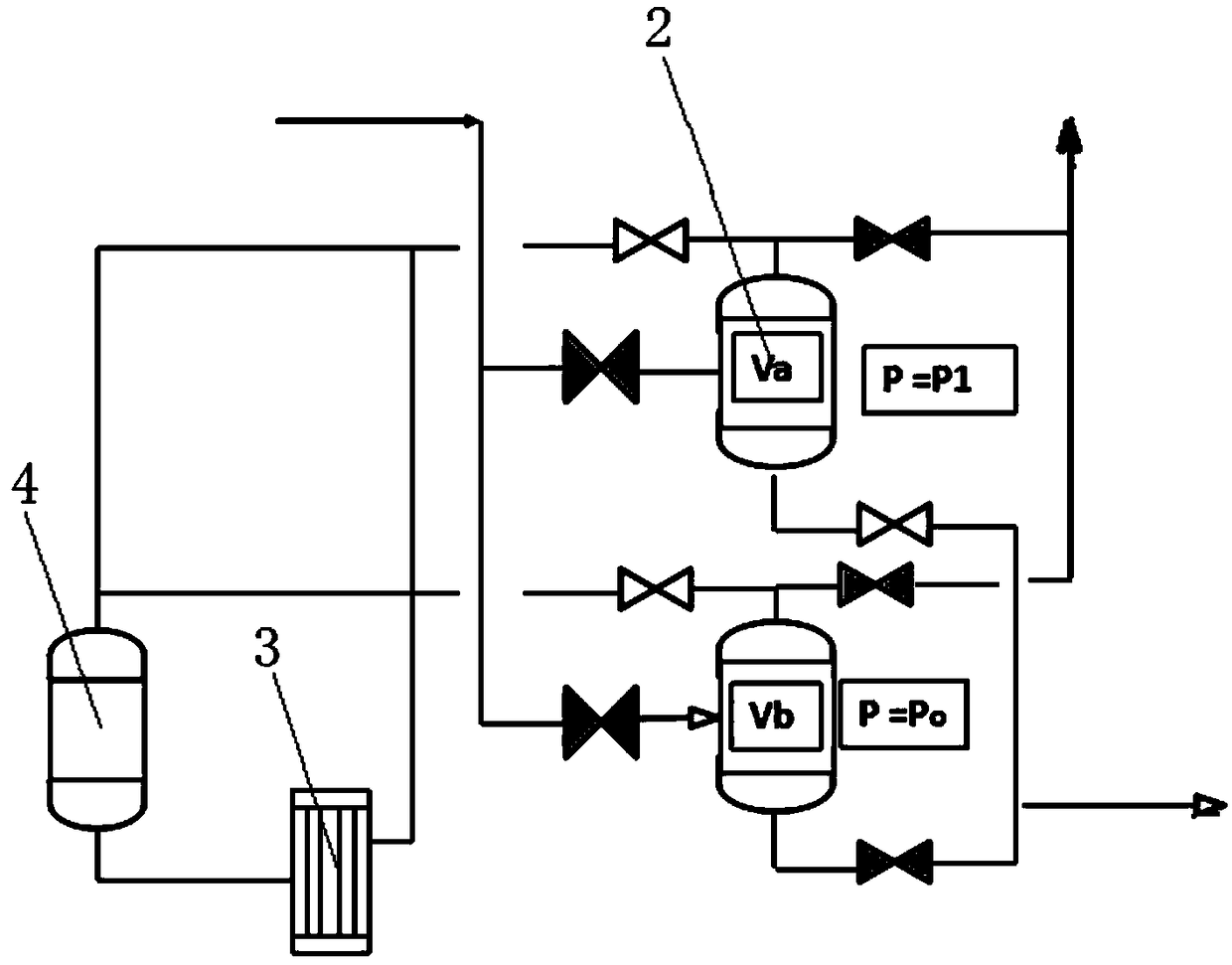
[0088] A pumpless pressurization process system of the present embodiment includes an LNG inlet 7, two sets of parallel booster tanks 2, an LNG outlet 8, a gas vent 9, a booster unit 3, an inert liquid storage tank 4 and a reliquefaction condensing 5, the first input end of the booster tank 2 is connected to the LNG inlet 7; the first output end of the booster tank 2 is connected to the LNG outlet 8; the second input end of the booster tank 2 is connected to the output end of the booster unit 3, and the booster The output end of the unit 3 is also connected to the input end of the inert liquid storage tank 4; the input end of the booster unit 3 is connected to the output end of the inert liquid storage tank 4; the second input end of the booster tank 2 is also connected to the gas vent 9; the reliquefaction condenser 5 It is arranged between the inert liquid storage tank 4 and the pressurization unit 3, and is used to condense the inert gas into liquid.
[0089] Specifically, two
PUM
 Abstract
Description
Claims
Application Information
 - R&D Engineer
- R&D Manager
- IP Professional
- Industry Leading Data Capabilities
- Powerful AI technology
- Patent DNA Extraction
Browse by: Latest US Patents, China's latest patents, Technical Efficacy Thesaurus, Application Domain, Technology Topic.
© 2024 PatSnap. All rights reserved.Legal|Privacy policy|Modern Slavery Act Transparency Statement|Sitemap