Heat dissipation device for refrigerator

A technology for heat sinks and refrigerators, which is used in household refrigeration devices, applications, household appliances, etc., can solve problems such as slow heat dissipation from heat sinks

Inactive Publication Date: 2018-11-23
SUIYANG COUNTY NAIHUAN ALUMINUM IND
View PDF6 Cites 0 Cited by
  • Summary
  • Abstract
  • Description
  • Claims
  • Application Information

AI Technical Summary

Problems solved by technology

[0004] The present invention intends to provide a cooling device for refr

Method used


Image

  • Heat dissipation device for refrigerator

Examples


Embodiment Construction

[0011] Further detailed explanation through specific implementation mode below:

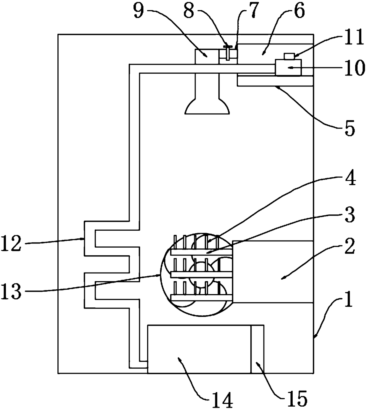
[0012] The reference signs in the drawings of the description include: refrigerator box 1, compressor 2, superconducting heat pipe 3, cooling fin 4, support plate 5, water storage tank 6, water outlet pipe 7, valve 8, water spray nozzle 9, water pump 10. Electromagnetic switch 11, water guide pipe 12, cooling fan 13, water collecting tank 14, water level detector 15.

[0013] The embodiment is basically as attached figure 1 Shown: a cooling device for a refrigerator, including a refrigerator box 1 and a compressor 2, the compressor 2 is provided with a superconducting heat pipe 3, the refrigerator box 1 is provided with a support plate 5, and the support plate 5 is provided with The water storage tank 6, the side wall provided on the water storage tank 6 is connected with a water outlet pipe 7, the water outlet pipe 7 is provided with a valve 8, and the end of the water outlet pipe 7 is provided wi


PUM

PropertyMeasurementUnit
The inside diameter ofaaaaaaaaaa
Thicknessaaaaaaaaaa

Abstract

The invention discloses a heat dissipation device for a refrigerator. The heat dissipation device includes a refrigerator body and a compressor. Superconducting heat tubes are arranged on the compressor. A supporting plate is arranged on the refrigerator body, a water storage tank is arranged on the supporting plate, and the side wall arranged on the water storage tank communicates with a water outlet tube. A valve is arranged on the water outlet tube, a water-spraying spray head is arranged at the tail end of the water outlet tube and located over the superconducting heat tubes, and spray holes of the water-spraying spray head directly face the superconducting heat tubes. A water collecting tank is arranged under the superconducting heat tubes and communicates with a water guiding tube. The end, away from the water collecting tank, of the water guiding tube communicates with the water storage tank, and a water pump is arranged at the end, close to the water storage tank, of the waterguiding tube and fixed to the supporting plate. The middle section of the water guiding tube is spiral. A heat dissipation fan is further arranged on the refrigerator body and directly faces the superconducting heat tubes. In the scheme, water and wind are utilized to quickly take away heat on the superconducting heat tubes, and thus the effect of accelerating heat dissipation effect is achieved.

Description


Claims


Application Information

Patent Timeline
Owner SUIYANG COUNTY NAIHUAN ALUMINUM IND
Why Eureka
Try Eureka