Computer cooling fan convenient to install

A cooling fan and computer technology, applied in the direction of electrical digital data processing, digital processing power distribution, instruments, etc., can solve the problems of time-consuming, inconvenient installation of cooling fans, inconvenient maintenance, etc., to achieve improved stability, easy installation, and fast The effect of installation

Pending Publication Date: 2020-09-08
惠州市建文鑫五金制品有限公司
View PDF0 Cites 0 Cited by
  • Summary
  • Abstract
  • Description
  • Claims
  • Application Information

AI Technical Summary

Problems solved by technology

[0004] The invention proposes an easy-to-install computer cooling fan, which solves the problem that the existing coo

Method used


Image

  • Computer cooling fan convenient to install
  • Computer cooling fan convenient to install
  • Computer cooling fan convenient to install

Examples


Embodiment Construction

[0023] The following will clearly and completely describe the technical solutions in the embodiments of the present invention with reference to the accompanying drawings in the embodiments of the present invention. Obviously, the described embodiments are only some, not all, embodiments of the present invention.

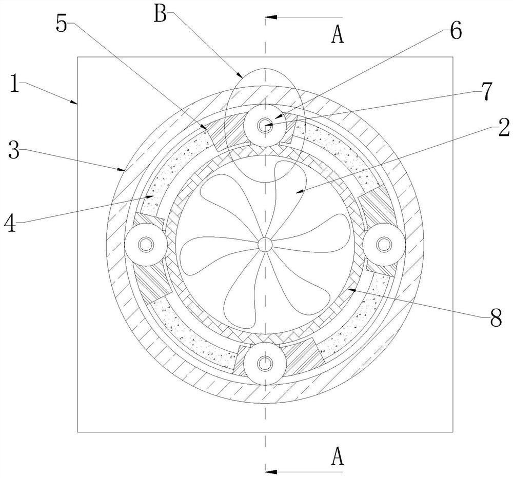
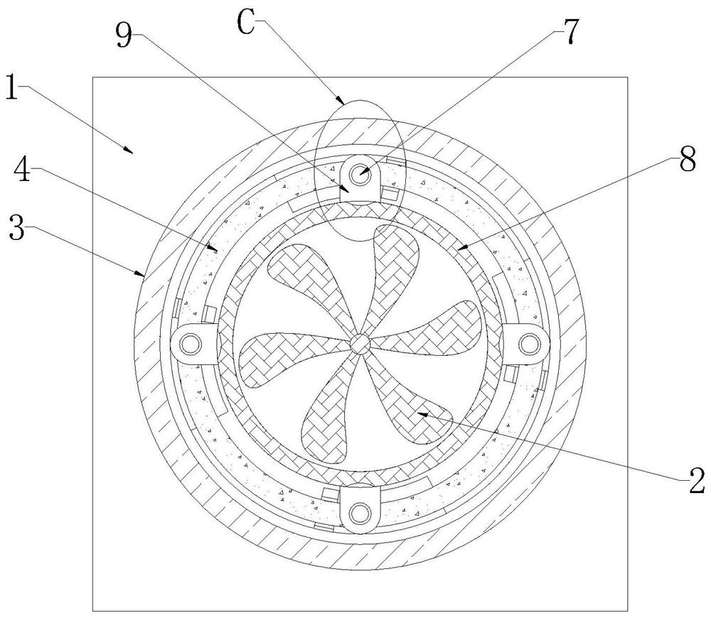
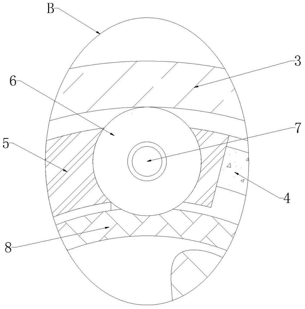
[0024] refer to Figure 1-6 , a computer cooling fan that is easy to install, including a main casing plate 1, an adjusting gear ring 3, a fixed plate 5, a pressing spring 11, an installation sleeve 8 and a cooling fan 2, the inner side of the main casing plate 1 is rotated and installed with Adjust the ring gear 3, and the inner side of the main casing plate 1 is fixedly connected with a fixed plate 5, the fixed plate 5 is located inside the adjustable gear ring 3, and the inner wall of one side of the fixed plate 5 is fixedly connected with a spring 11, and The end of the pressing spring 11 is fixedly connected with the movable ring 4, the cooling fan 2 is installed i


PUM


Abstract

The invention discloses a computer cooling fan convenient to install and relates to the field of computer heat dissipation. The computer cooling fan is provided to solve the following problems in theprior art that: existing cooling fans are inconvenient to install, so that the maintenance of existing cooling fans is inconvenient after a fault occurs and a large amount of time are consumed. The invention provides the following scheme: the computer cooling fan comprises a host shell plate, an adjusting gear ring, a fixing plate, an abutting spring, a mounting sleeve and a cooling fan. An adjusting gear ring is rotationally installed on the inner side of the main machine shell plate. And the inner side of the main machine shell plate is fixedly connected with a fixed plate, the fixed plate is located in the adjusting gear ring, the inner wall of one side of the fixed plate is fixedly connected with an abutting spring, the end of the abutting spring is fixedly connected with a movable ring, a cooling fan is installed in the installation sleeve, and the installation sleeve is located between the fixed plates. The computer cooling fan fixing device is novel in structure, the traditionaloperation step of installing screws one by one is changed, and a computer cooling fan can be quickly and stably installed and can be effectively fixed.

Description


Claims


Application Information

Patent Timeline
Owner 惠州市建文鑫五金制品有限公司
Why Eureka
Try Eureka