Positioning device for go-no gauge detecting device

A positioning device and detection device technology, applied in the direction of measuring devices, mechanical measuring devices, mechanical devices, etc., can solve the problem of accurate positioning of go-no-go gauges, etc.

Pending Publication Date: 2018-11-23
东莞市瑞科智能科技有限公司
View PDF1 Cites 0 Cited by
  • Summary
  • Abstract
  • Description
  • Claims
  • Application Information

AI Technical Summary

Benefits of technology

This technology allows for better accuracy during production processes where products are being transported or processed through various machines such as printing presses. It involves placing these items onto an immovable surface called a fixation plate before they can be used with other machinery like printers. To ensure accurate placement, it uses sensors attached at specific locations around its edges to detect if there has been any holes present within them. Once detected, this sensor sends signals back into the machine's computer controller which then adjusts certain features (such as motions) accordingly based upon their location inside each area.

Problems solved by technology

This patented technology solves this issue by making sure each part inside your production line has its own special type of gage called a geckle or stop gauge, which allows only certain holes passing through them. However, there may also have other types like a runway gauge where some holes don't work well (known as deadlock). To address these issues, an apparatus called a positioner needs to ensure accurate placement of the Go-No-Go gauge into specific areas within the production process.

Method used


Image

  • Positioning device for go-no gauge detecting device
  • Positioning device for go-no gauge detecting device
  • Positioning device for go-no gauge detecting device

Examples


Embodiment Construction

[0018] In order to enable those skilled in the art to better understand the technical solution of the present invention, the product of the present invention will be further described in detail below in conjunction with the embodiments and accompanying drawings.

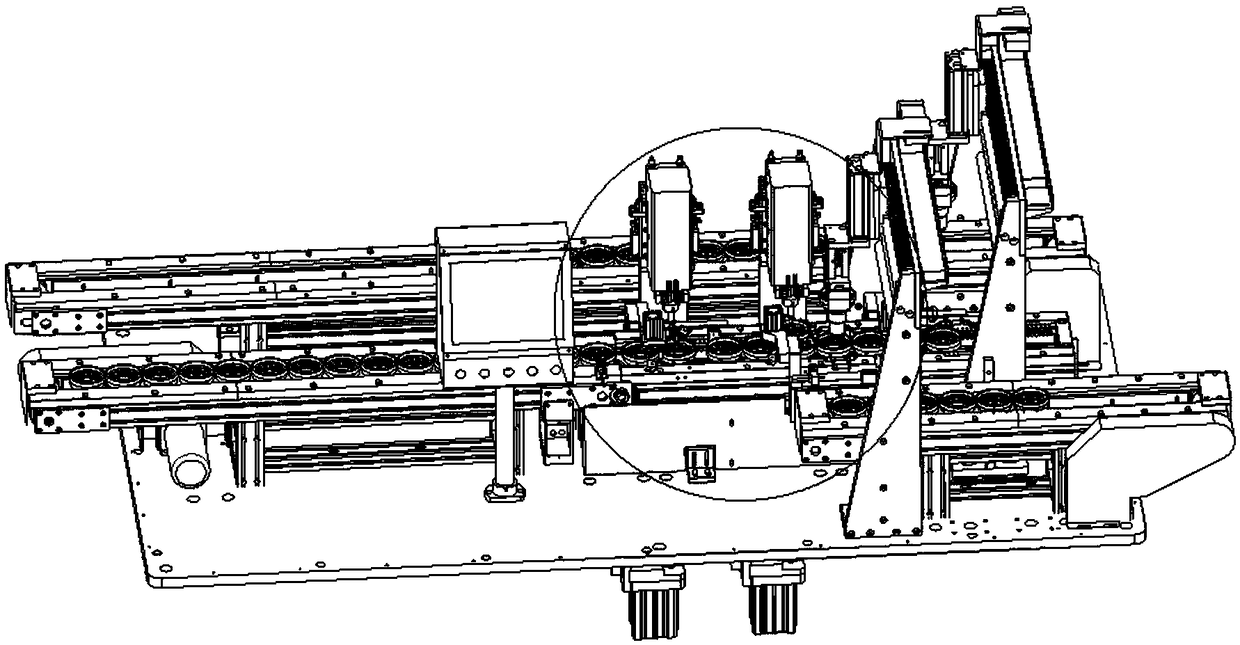
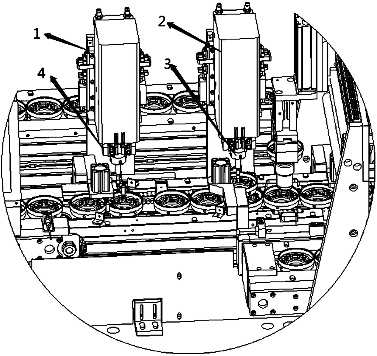
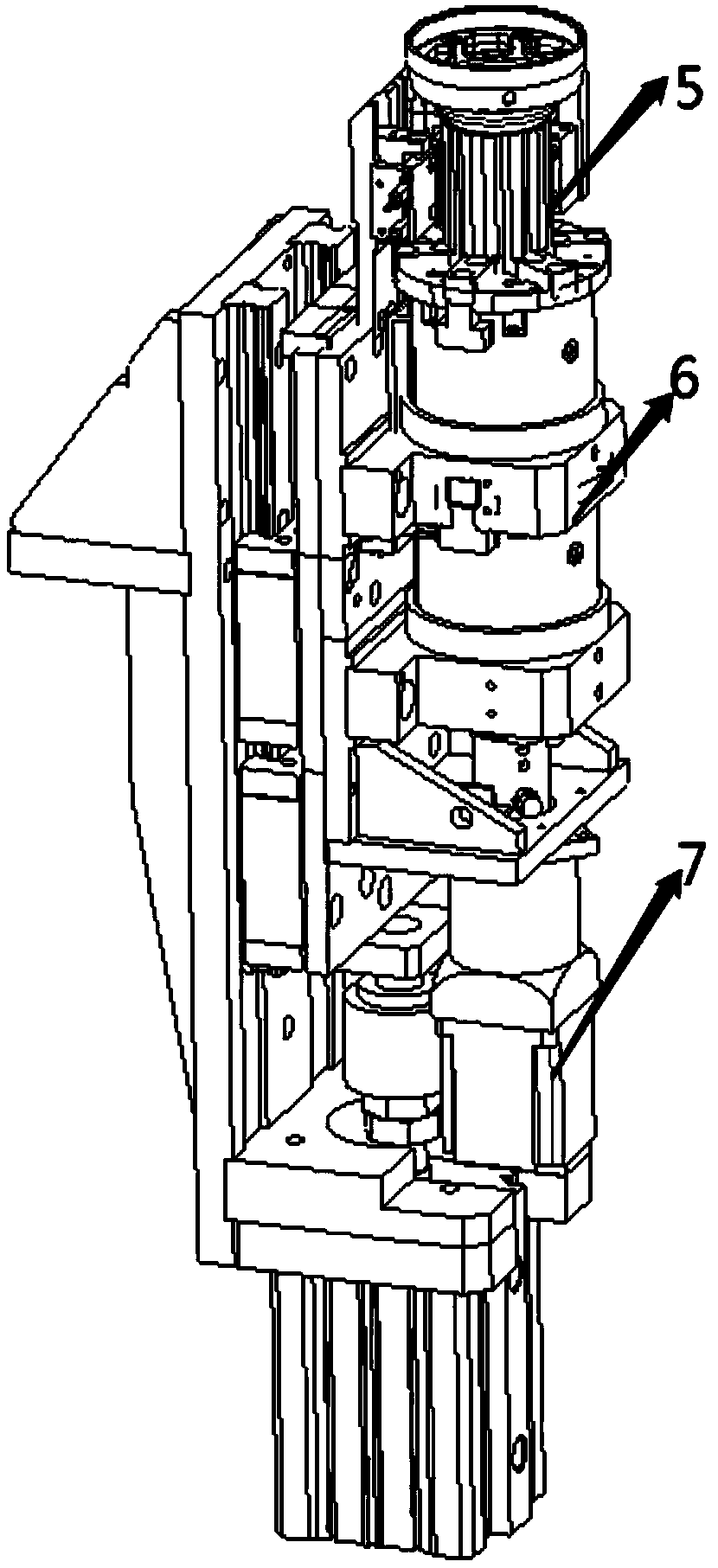
[0019] Such as Figure 1-5 As shown, a positioning device of a go-no-go gauge detection device, the go-no-go gauge detection device includes a drive device and a go-no-go gauge detection device, the drive device is connected to the go-no-go gauge detection device, and the go-no-go gauge detection device The device includes a go-no-go gauge detection piece;

[0020] It is characterized in that: the go-no-go gauge detection equipment also includes the positioning device and a PCB control system, the positioning device includes a detection camera, a fixing piece, a fixed cylinder, and a servo motor, and the detection camera is set on the go-no-go gauge On the detection part, the fixed part is arranged on the fixed cylinde


PUM


Abstract

The invention discloses a positioning device for a go-no gauge detecting device. With a fixation member and a fixation cylinder, when a product is placed on the fixation member, the fixation cylinderis driven and thus the fixation member contracts to grasp the product, so that the product is fixed on the fixation member. The fixation member is arranged right below a go-no gauge detecting element.A detection camera is arranged at the go-no gauge detecting element and is used for shooting the product and transmitting data to a PCB control system; the PCB control system determines the locationof a hole; when a to-be-detected hole of the product is not at a station, the PCB control system controls a servo motor to rotate the corresponding angle and thus the hole is located at the station, thereby realize positioning.

Description


Claims


Application Information

Patent Timeline
Owner 东莞市瑞科智能科技有限公司
Why Eureka
Try Eureka