Communication control system for charging navigation of new energy vehicles

A new energy vehicle and communication control technology, applied in the field of new energy vehicles, can solve problems such as waste of resources, uneven traffic flow distribution, inability to meet vehicle charging and power grid, and achieve the effect of improving automation

Inactive Publication Date: 2018-12-14
宁波市鄞州智伴信息科技有限公司
View PDF5 Cites 0 Cited by
  • Summary
  • Abstract
  • Description
  • Claims
  • Application Information

AI Technical Summary

Benefits of technology

The technical effect that this invention improves upon how well it works for automatic or intelligent systems by providing accurate data on what charges are being charged at each station's location.

Problems solved by technology

This patented describes an autonomous vehicle-charged navigational control (AVC) that uses sensors on its own to determine if cars will arrive at their destinations accurately without wasting any time or energy by calculating how much they should be charged with batteries based solely upon factors like distance from other sources such as road signs or weather conditions. However, this method does not take into account all possible routes between different locations where electricity may have been interrupted during peak hours. Additionally, current methods require manual intervention to adjust routing paths after each charge has completed, making them difficult to manage effectively over longer periods of use.

Method used


Image

  • Communication control system for charging navigation of new energy vehicles
  • Communication control system for charging navigation of new energy vehicles
  • Communication control system for charging navigation of new energy vehicles

Examples


Embodiment Construction

[0037] The present invention will be further described below in conjunction with specific embodiment:

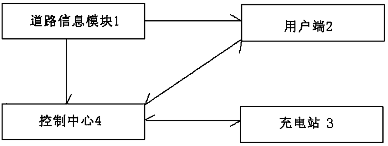
[0038] A communication control system for new energy vehicle charging and navigation, wherein the new energy vehicle charging and navigation part includes a road information module 1, a user terminal 2, a control center 4 and a charging station 3; the signal output terminals of the road information module 1 are connected to the The signal input terminal of the user terminal 2 is connected to the signal input terminal of the control center 4; the user terminal 2 and the control center 4 are connected by two-way communication; the control center 4 is connected by two-way communication with the charging station 3;

[0039] Among them, the communication control between the charging station 3 and the control center 4 is carried out through the following parts:

[0040] The communication interaction module is used for the control center 4 to send a communication request signal to the


PUM


Abstract

The invention discloses a communication control system for charging navigation of a new energy vehicle, which comprises the following parts: a road information module 1, a user terminal 2, a control center 4 and a charging station 3; The invention greatly improves the automation and intelligence level of the charging navigation control system by carrying out real-time and on-line verification on the charging station.

Description


Claims


Application Information

Patent Timeline
Owner 宁波市鄞州智伴信息科技有限公司
Why Eureka
Try Eureka