A rail rotary plug-and-pull type socket

A technology of plug-in and plug-in sockets, which is applied in the field of orbital rotary plug-in sockets, can solve the problems of messy use of wiring harnesses, inability to expand sockets, and lack of mobility, etc., and achieve simple appearance, good use effects, and improved use efficiency Effect

Inactive Publication Date: 2018-12-18
WUXI HOUFA AUTOMATIC EQUIP CO LTD
View PDF0 Cites 0 Cited by
  • Summary
  • Abstract
  • Description
  • Claims
  • Application Information

AI Technical Summary

Problems solved by technology

[0002] Socket, also known as power socket, switch socket, and socket refers to a seat that one or more circuit connections can be inserted, through which various connections can be inserted, and the final removal can be achieved by connecting and disconnecting between lines and copper parts. Electrical purposes; the existing sockets are divided into wall sockets and plug-in boards. The wall sockets are installed with the wiring and are completely immobile, and the jacks cannot be expanded. The plug-in boards take power through the socket body and extend out. The wiring harness The clutter also greatly reduces the experience of use

Method used


Image

  • A rail rotary plug-and-pull type socket
  • A rail rotary plug-and-pull type socket
  • A rail rotary plug-and-pull type socket

Examples


Example Embodiment

[0020] The specific embodiments of the present invention will be described in further detail below with reference to the accompanying drawings.

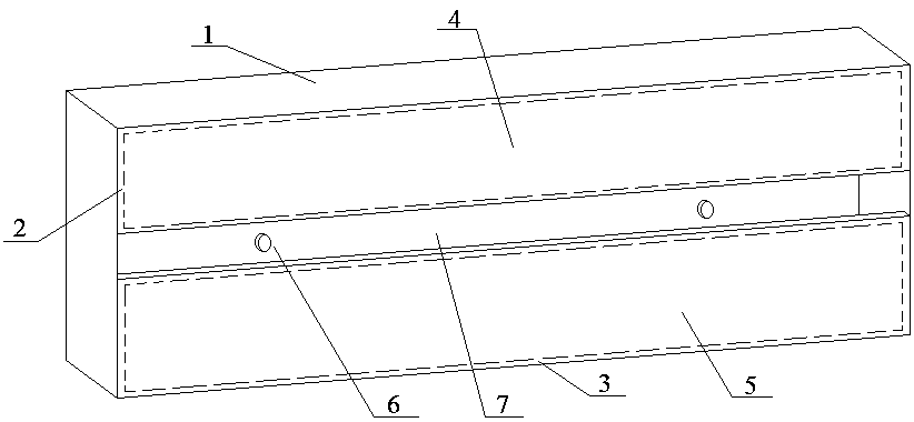
[0021] like figure 1 As shown, the present invention designs an orbital rotary plug-in socket, which includes a base and at least one socket body; wherein, the base includes a base box 1, an upper rectangular cover 2, a lower rectangular cover 3, and an upper conductive plate 4. and the lower conductive plate 5; the base box 1 is in the shape of a cuboid, and one of the sides where the long side and the broad side of the base box 1 are coplanar is set to be open; the thickness of the upper rectangular cover plate 2 is equal to the thickness of the lower rectangular cover plate 3 , the length of the long side of the upper rectangular cover plate 2 and the length of the long side of the lower rectangular cover plate 3 are equal to the length of the upper long side of the base box 1, and the width of the upper rectangular cover plate 2 and


PUM


Abstract

The invention relates to a rail rotary plug-and-pull socket, adopts a completely new structural design, the socket is divided into a base and a socket body structure, A chute structure is designed forthe base, in cooperation with an I-shaped structure of the socket body, so that the insertion, rotation, and butt joint use of the socket body relative to the chute structure of the base can be realized, As the fire line correspond to each other in the chute structure of the base, The socket body can be arranged at any position in the base sliding slot structure according to the usage habit. At the same time, the number of the socket body can be expanded based on the length of the base sliding slot, which greatly improves the use efficiency.

Description


Claims


Application Information

Patent Timeline
Owner WUXI HOUFA AUTOMATIC EQUIP CO LTD
Why Eureka
Try Eureka