Marine oil spill recovery device based on air grid

An offshore oil spill and grid technology, which is applied in general water supply conservation, open water surface cleaning, water conservancy projects, etc.

Active Publication Date: 2018-12-21
HARBIN ENG UNIV
View PDF6 Cites 1 Cited by
  • Summary
  • Abstract
  • Description
  • Claims
  • Application Information

AI Technical Summary

Problems solved by technology

Biological treatment is a method of oil spill treatment using certain microorganisms naturally present in the ocean or soil that have a strong ability to oxidize and

Method used


Image

  • Marine oil spill recovery device based on air grid
  • Marine oil spill recovery device based on air grid
  • Marine oil spill recovery device based on air grid

Examples


specific Embodiment approach

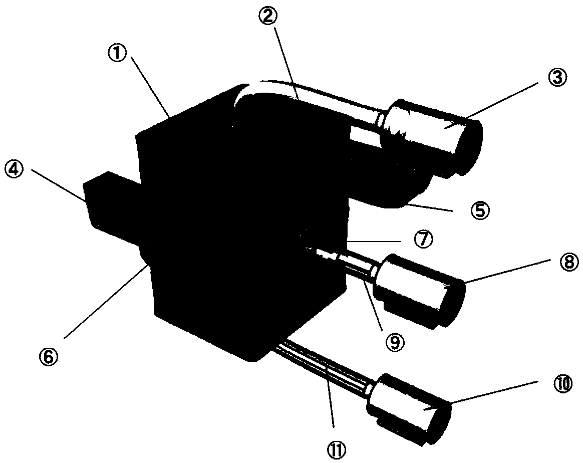
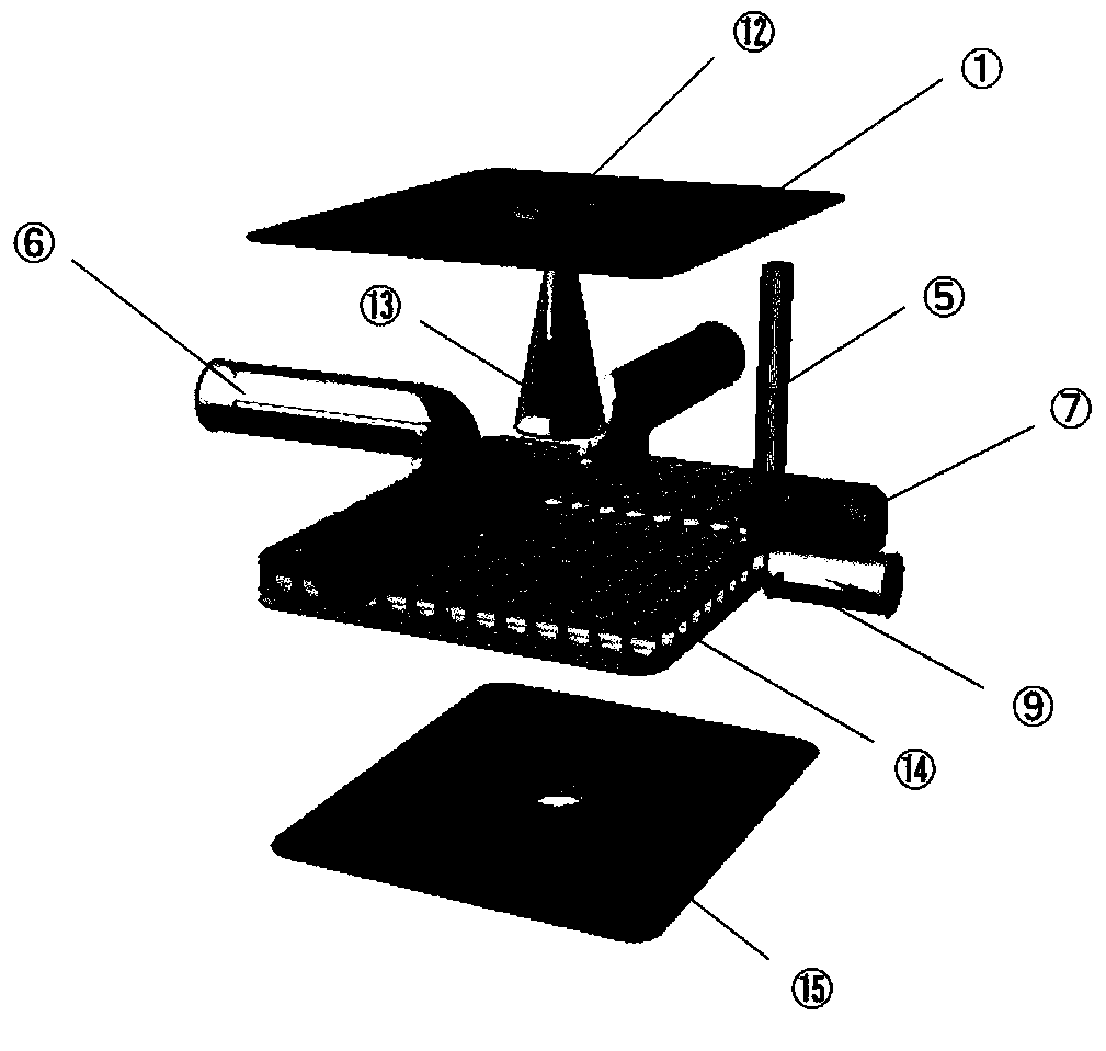
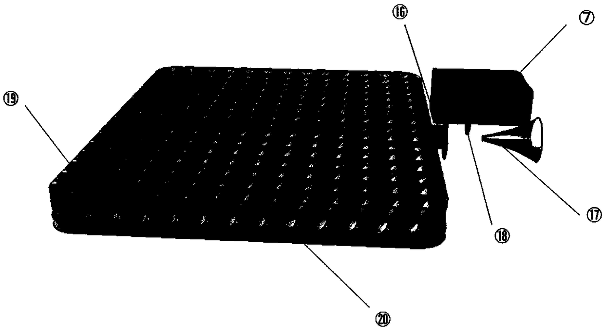
[0016] Figure 1 to Figure 3 They are the perspective view of the oil spill recovery device, the internal view of the oil spill recovery device and the partial view of the bubble generating device. The marine oil spill recovery device based on the air grid designed by the present invention is mainly composed of a box body 1, an oil suction pipeline 2, an oil pump 3, a floating body 4, an emulsifier inlet 5, an oil-water circular pipe 6, an emulsifier storage box 7, and a high-pressure air pump 8. High-pressure gas pipeline 9, water pump 10, water-suction pipeline 11, oil suction port 12, funnel-shaped oil cover 13, round pipe grid 14, water suction port 15, high-pressure gas inlet 16, high-pressure gas nozzle 17, emulsifier outlet 18 , Horizontal pipe 19, vertical pipe 20 constitute.

[0017] combine Figure 1 to Figure 3 , the working process of the present invention is as follows:

[0018] (1) The device is placed on the sea surface, with a floating body 4 on each side of th


PUM


Abstract

The invention provides a marine oil spill recovery device based on an air grid, and belongs to the field of marine oil spill recovery devices; the marine oil spill recovery device based on the air grid is placed on the sea surface, an air pump, a water pump and an oil pump are placed on a ship, a water suction pump and the air pump are turned on, pressure in an oil cleaning device box body is lowered, the water enters the oil cleaning device box body through an oil water round tube, and high pressure gas passes out from a nozzle through a high pressure pipe, and emulsifier from an emulsifier box is atomized into a circular tube grid. Since the upper end of a round tube is provided with air holes, the gas overflows from the air holes and floats upward with a small density of oil. At the same time, the emulsifier makes the oil become free, and makes bubbles float up to the surface easier. A funnel-type oil cover contacts the oil surface to form a closed space, and then the oil pump pumpsthe floating oil for recycling. The marine oil spill recovery device based on the air grid utilizes the bubble to make the physical method of oil and water layer to separate and recover the oil and water, has the characteristics of green environmental protection, convenient and easy operation, high recovery efficiency, and application prospect is broad.

Description


Claims


Application Information

Patent Timeline
Owner HARBIN ENG UNIV
Why Eureka
Try Eureka