Camera-based modular electronic exterior mirror system and use method thereof, commercial vehicle
An exterior rear-view mirror, modular technology, applied in vehicle components, optical observation devices, transportation and packaging, etc., can solve the problems of narrow adaptability, poor image display quality, weak rear-view guidance effect, etc., and achieve adjustability. Strong, comprehensive display, strong rear-view guidance effect
- Summary
- Abstract
- Description
- Claims
- Application Information
AI Technical Summary
Benefits of technology
Problems solved by technology
Method used
Image

Examples
Embodiment 1
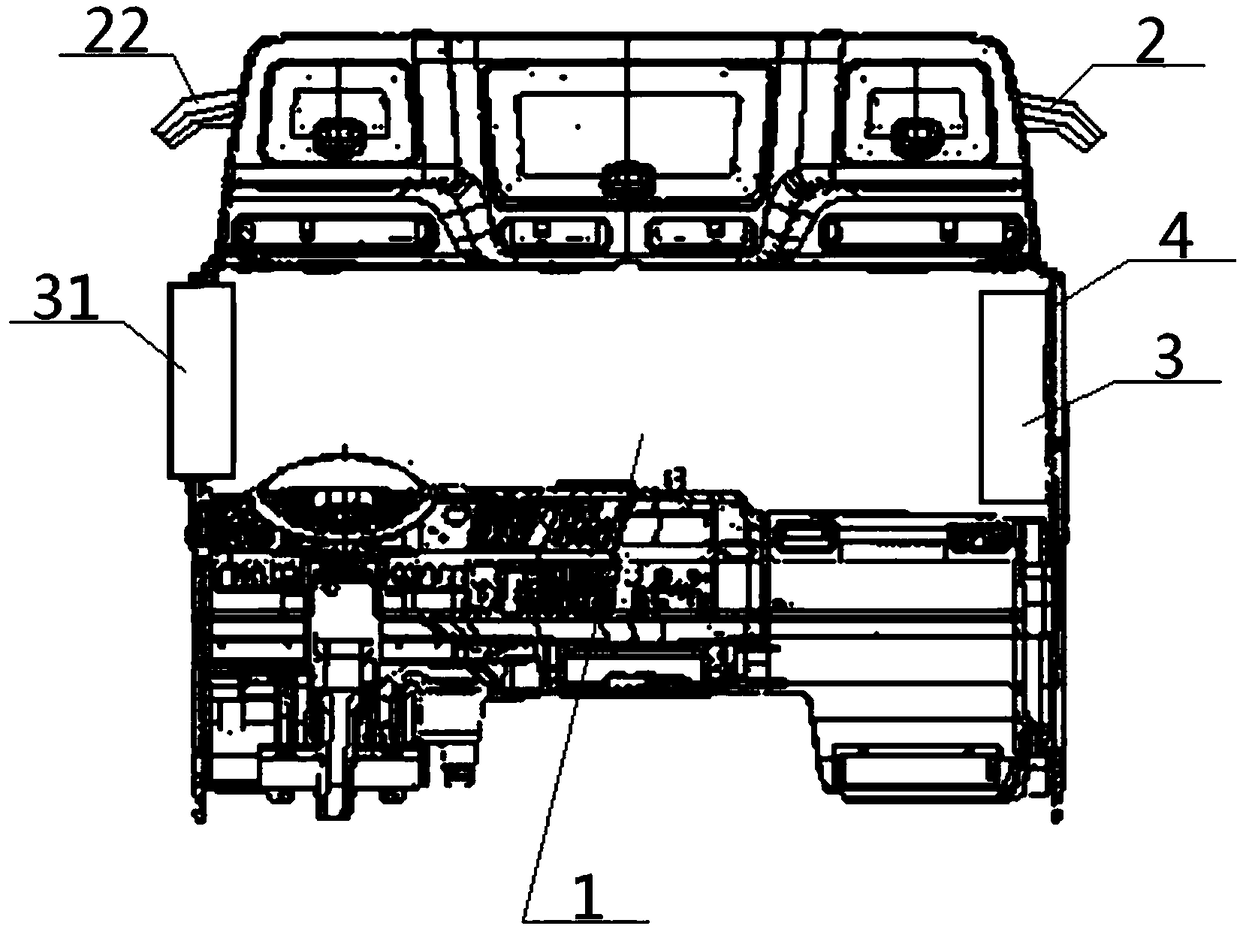
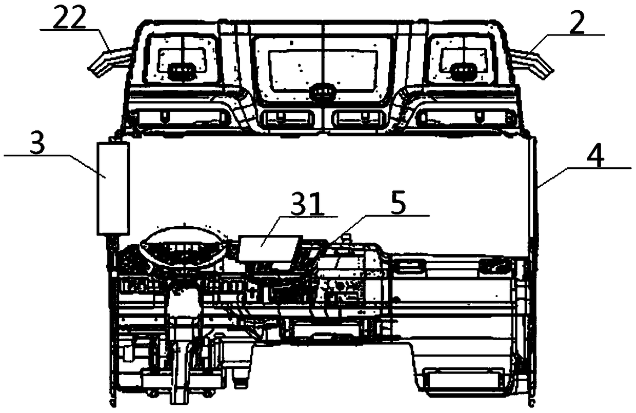
[0054] see Figure 1 to Figure 6 , a camera-based modular electronic exterior mirror system, including a camera assembly 2 and a display assembly 3, the camera assembly 2 is installed outside the cab 1, and the camera assembly 2 and the display assembly 3 Carry out signal connection; Described camera assembly 2 comprises camera module 21, camera support 22 and camera wiring harness 23, described camera module 21, camera support 22 are all positioned at the outside of driver's cab 1, the outside of camera support 22 and driving Cab 1 is connected, and camera module 21 is installed inside camera support 22, and camera module 21 is connected with one end of camera wire harness 23, and the other end of camera wire harness 23 penetrates into cab 1 from the outside of cab 1 and communicates with the display assembly. The image processing unit 32 in Cheng 3 carries out signal connection; Described display assembly 3 comprises display screen 31 and image processing unit 32, and the input
Embodiment 2
[0059] Basic content is the same as embodiment 1, the difference is:
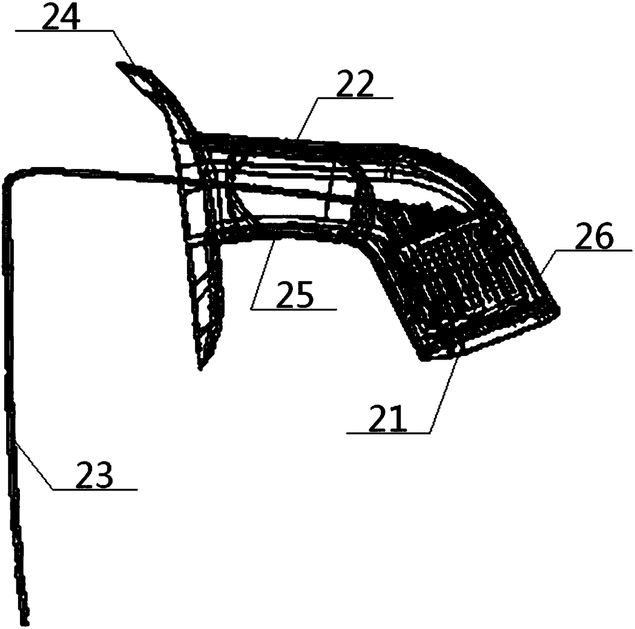
[0060] The camera support 22 includes a connecting portion 24, a middle supporting portion 25 and a mounting portion 26, and the inner end of the mounting portion 26 is connected with the cab 1 through the middle supporting portion 25 and the connecting portion 24 successively. 24. The angle between the middle bearing part 25 is an acute angle, the angle between the middle bearing part 25 and the installation part 26 is an obtuse angle, and the intersection of the middle bearing part 25 and the installation part 26 is a circular arc structure, and the middle bearing Both the part 25 and the mounting part 26 are hollow structures, and the cavity of the mounting part 26 is connected with the camera module 21 . Preferably, the camera module 21 adopts a wide-angle lens.
Embodiment 3
[0062] Basic content is the same as embodiment 1, the difference is:
[0063]The camera module 21 is connected to the inner cavity of the mounting part 26 through buckles and bolts; there are six positions connected to the connecting part 24 on the cab 1, which are respectively: the front end 11 at the bottom of the cab window, the cab Window bottom rear end 12, cab window top front end 13, cab window top rear end 14, roof front end 15, car cover cover front end 16; described cab window bottom front end 11, cab window bottom rear end 12, driving Cab window top front end 13, cab window top rear end 14 are positioned at the four corners of cab 1 respectively, and the heights of roof front end 15, cab window top front end 13, cab window bottom front end 11, and car cover front end 16 decrease successively.
PUM
 Abstract
Description
Claims
Application Information
 - R&D Engineer
- R&D Manager
- IP Professional
- Industry Leading Data Capabilities
- Powerful AI technology
- Patent DNA Extraction
Browse by: Latest US Patents, China's latest patents, Technical Efficacy Thesaurus, Application Domain, Technology Topic.
© 2024 PatSnap. All rights reserved.Legal|Privacy policy|Modern Slavery Act Transparency Statement|Sitemap