Electrical connector and combination thereof

A technology of electrical connectors and contact arms, applied in the direction of connection, fixed connection, welding/welding connection, etc., which can solve the problem of reducing the service life of socket connectors, unfavorable plugging operations of plug connectors and socket connectors, and damage to socket terminals, etc. problem, achieve the effect of reducing the maximum insertion force, increasing the service life and reducing signal interference

Active Publication Date: 2019-01-11
DEYI PRECISION ELECTRONIC IND CO LTD PANYU
View PDF5 Cites 0 Cited by
  • Summary
  • Abstract
  • Description
  • Claims
  • Application Information

AI Technical Summary

Benefits of technology

This new design improves upon existing connectors by allowing for better control over signals transmitted through each individual connection point on an electronic device's circuit board (PCB). By positioning both end points above or below one another, there will reduce interference from other connections while still maintain stable communication speed. Additionally, this design allows for more precise placement of pin contacts without increasing their overall size.

Problems solved by technology

The technical problem addressed by this patented technology relates to improving upon existing connectors that have high insertions forces during use without damaging their connections or causing discomfort on users' hands while connecting them together.

Method used


Image

  • Electrical connector and combination thereof
  • Electrical connector and combination thereof
  • Electrical connector and combination thereof

Examples


Embodiment Construction

[0044] In order to facilitate a better understanding of the purpose, structure, features, and effects of the present invention, the present invention will now be further described with reference to the drawings and specific embodiments.

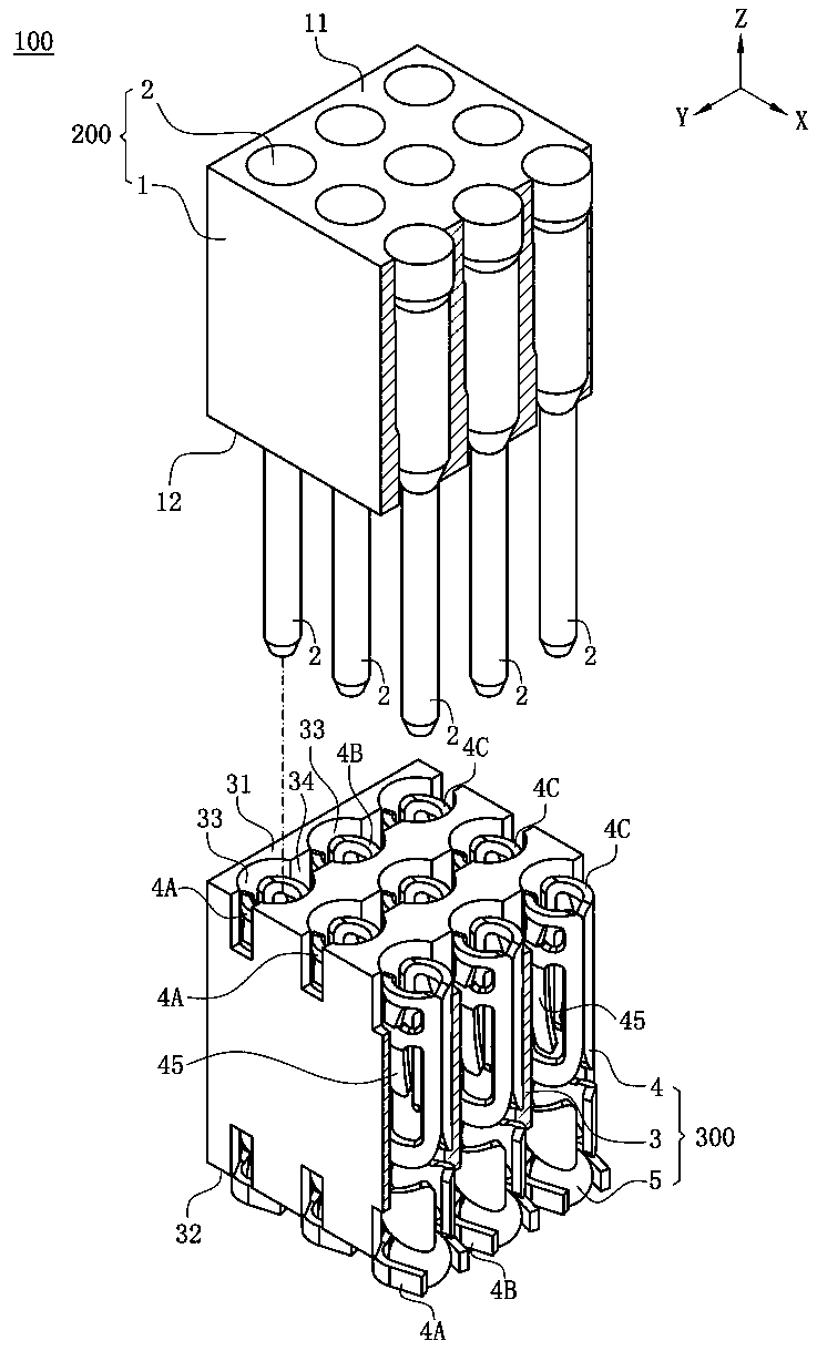
[0045] Such as figure 1 As shown, the electrical connector assembly 100 of the present invention defines a front-rear direction X, a left-right direction Y and a vertical direction Z perpendicular to the front-rear direction X.

[0046] Such as figure 1 with Figure 7 As shown, the electrical connector assembly 100 of the present invention includes a plug 200, an electrical connector 300 mated with the plug 200, and a circuit board 400 welded under the electrical connector 300.

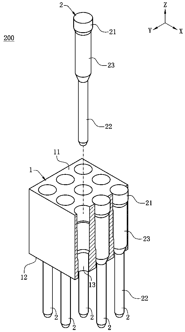
[0047] Such as figure 2 As shown, the plug 200 includes a base 1 and a plurality of pins 2 fixed to the base 1.

[0048] Such as figure 2 with Figure 5 As shown, the base 1 is made of insulating material. The base 1 has a top surface 11 and a bottom surface 12 opposite to eac


PUM


Abstract

The invention discloses an electrical connector for a plug with a plurality of pins to be inserted downward, comprising a body, wherein the body is provided with a plurality of receiving holes penetrating the upper surface and the lower surface of the body; Multiple terminals, corresponding to the plurality of accommodation holes, the upper ends of the plurality of said terminals are located at the same height, and the lower ends of the plurality of said terminals are located at the same height, each of the terminals has two contact arms that are opposite and close to each other. The two contact arms of a plurality of the terminals are located at different heights and are provided for successively downward insertion of a plurality of the pins corresponding thereto, thereby reducing not only signal interference between the plurality of the terminals, but also maximum insertion force for the plug inserted into the electrical connector.

Description


Claims


Application Information

Patent Timeline
Owner DEYI PRECISION ELECTRONIC IND CO LTD PANYU
Why Eureka
Try Eureka