Steam turbine equipment related method

An equipment-related, steam turbine technology, applied in the cleaning field, achieves the effect of simple structure and convenient operation

Inactive Publication Date: 2019-01-15
斯丹红
View PDF0 Cites 0 Cited by
  • Summary
  • Abstract
  • Description
  • Claims
  • Application Information

AI Technical Summary

Problems solved by technology

[0002] Steam turbine is the main equipment of modern thermal power plants, and is also used in metallurgy, chemistry, ships and other fields. It forms a complete set of equipment with condensers and heaters. The condenser condenses the exhaust steam of the steam turbine into water to increase efficiency. The steam turbine will produce scale and other impurities that need to be cleaned. The current preliminary cleaning is mostly manual scraping and manual high-pressure water. Therefore, it is necessary to design a simple and effective method related to steam turbine equipment.

Method used


Image

  • Steam turbine equipment related method
  • Steam turbine equipment related method
  • Steam turbine equipment related method

Examples


Example Embodiment

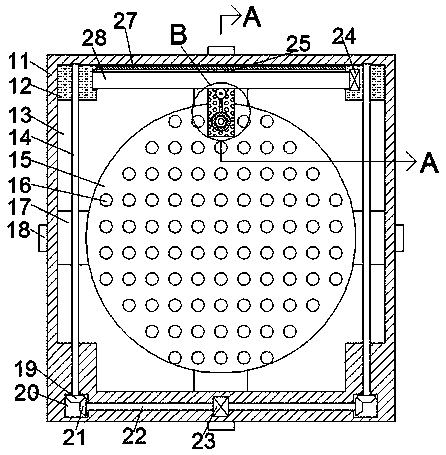
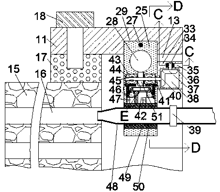
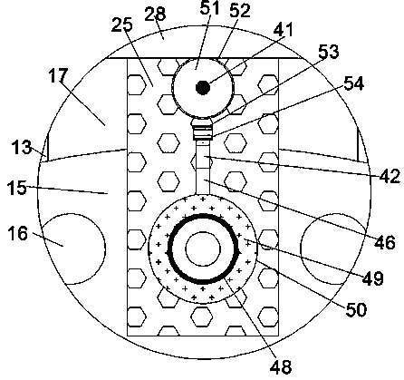
[0021] Such as Figure 1-Figure 6 As shown, a steam turbine equipment related method of the present invention, the equipment used in this method includes a device body 11, a transmission device provided in the device body 11, a telescopic device provided in the device body 11, and The moving device in the device main body 11, the transmission device includes a first cavity 13 arranged in the device main body 11 to penetrate back and forth, and the upper inner wall of the first cavity 13 communicates with each other. There is a second cavity 29, a first sliding block 25 is slidably arranged in the second cavity 29, the lower end of the first sliding block 25 extends into the first cavity 13, and the first A first rotating cavity 52 is provided in a sliding block 25, a turbine 51 is rotatably arranged in the first rotating cavity 52, and a first rotating shaft 41 is fixedly connected to the turbine 51. A second rotating cavity 43 is symmetrically provided in the side inner wall. Th


PUM


Abstract

The invention discloses a steam turbine equipment related method. Equipment used in the method comprises a device body, a transmission device arranged in the device body, a telescopic device arrangedin the device body and a moving device arranged in the device body; the transmission device comprises a first cavity which is arranged in the device body and is in front and back through, a second cavity communicates into the upper side inner wall of the first cavity, a first sliding block is arranged in the second cavity in a sliding manner, the lower end of the first sliding block extends and leads into the first cavity, a first rotation cavity is formed in the first sliding block, and a turbine is rotatably arranged in the first rotation cavity, and is fixedly connected with a first rotating shaft. The equipment is simple in structure and convenient to use, can be used for a high-pressure water gun to automatically carry out preliminary cleaning on a condenser, is easy to mount, saves manpower and is suitable for condensers of various models and worth recommendation.

Description


Claims


Application Information

Patent Timeline
Owner 斯丹红
Why Eureka
Try Eureka